A modular led light

Ooh one other idea - looks like your diffuser can be removed easily enough. Did you try using a thin veneer of the same kind of wood?

I make a logo sign based on this a few years ago, before Pixelblaze existed with an Electric Imp:

2 Likes

@petros, just awesome! Both the electronice and the woodworking. I agree that the Hackaday folks would love this.

(@jeff, that veneer sign is also super cool. Is that the 0.2mm paper/fabric-backed stuff? It’d be fun to use that effect on an office wall!)

2 Likes

As far as I know, it’s just the product you get when you ask for a “veneer”. The depth isn’t specified on my 2013 P.O., but I do remember that it seemed to be a radial spiral product, because the knot pattern repeated. In our project, it was a “birds eye maple veneer”, but I don’t think there was a backing material like paper or fabric. That might have been a bad idea, because after several years of heat from LEDs, the Veneer->E6000->Acrylic sandwich layers tended to warp a little and produce a front face that wasn’t flat.

1 Like

Correct, 3 wires per strip. I’m using 3 4-pin connectors to get a total of 2.5A(they are rated at 0.5A per pin). They can be connected on any of 4 sides, so they are not freely rotatable, only every 90 degrees with the screws of the male PCBs acting as guides.

I liked from the beginning the idea of having only one side lit, plus there is not enough room in the bricks for more sides. After testing a bit, I found that the ideal distance between the acrylic and the strip in order to get proper diffusion and not see the individual sources was about 1.5cm with a 3mm thick acrylic. Given the bricks are 3x3cm, not much space left!

Yes, all leds within a brick are individually addressable, but depending on the configuration there might be some forking. So for example the cube that you see in the photos has 120 pixels, but only 40 are addressable-I must say it took me a while to figure out how to wire the connecting cubes for this one.

The other day we did a couple of concentric 2D circles and used your map to great effect. Could you guide me on how to do one for the oval sphere in the photo below?

It’s got 25 pixels running downwards in the centre column, then 60 in every circle. I’m completely clueless as to how to map such an arrangement.

2 Likes

Trust me, when I was asking about the magnets I had no idea it would be like this either:)

I love what you did with the veneer, really cool looking and gives me ideas for the future:)

You all mention Hackaday, I hadn’t thought about that at all, I’ll give it a try.

In order to check how durable the whole thing was prior to giving it to my girlfriend, I gave it to my 4 and 5,5 year old children to play with-very scientific, I know:)- and they loved it. I’m now thinking of making a new version for them, same principles for the bricks but a new controller that will be a wooden board where they can place colored wooden chips and change patterns or pattern colors, it’s still a work in progress in my head but will post as I go.

2 Likes

Ok, so the key to mapping this oval shape (or any you could build) is to imagine it in 3D, pick a spot for reference (probably the top/start), and then use a set of values that make it easy to figure out the changes happening.

If you say the top of the shape is 0,0,0… Where the first value is the X (call it the blue axis), the second is the Y (call it the yellow axis), and the third value is Z (call it the red axis)

The first 25 pixels… Remain in the X = 0, Y = 0 range, but Z changes as it drops. Let’s say the values decrease as you move down, so the first led is 0,0,-1, then 0,0,-2, and so on. The bottom is 0,0,-25…

So now we’re at the bottom… We’ll move up the blue circle… Y will remain 0, while X (blue) will change as you move around it. Assuming it’s 6 segments of 10… The first 10, your X changes from 0 to 10… But the Z also increases back up, as it moves upward. If you did it exactly at whole values… It won’t quite line up, due to math… Half of 60 is 30, but you only have 25 vertical LEDs (levels) mapped, and the ones in the middle segment of the ovals are also vertical… so we want to fudge it on the diagonals. 25-10 (total vertical-oval vertical) is 15… Divided by 2 (2 diagonals) is 7.5 … So for your Z change, use 7.5/10 or .75 change So instead of 1,0,-24 then 2,0,-23, etc. Thru 10,0,-14… You actually need to 1,0,-24.25, then 2,0,-23.5, 3,0,-22.75, and so on…
Then the second segment, your X is constant (10, maybe 11, maybe 12? You can decide), your Y is still zero… And Z changes a full 1… Then third segment, X drops back down to 0 1 at a time, Y remains 0, Z continues to increase .75 each time…
That brings you to the top… Now X continues to reduce going negative… Y continues to be zero…
Z decreases as we drop again, by .75… Fifth segment, X is negative -11 (or -12, whatever value looks good), Y is zero, Z drops by -1… 6th segment: X increases back to 0, Y remains 0, Z drops by .75… Now at the bottom, you start the Y (yellow) loop, which is exactly the SAME as above, just reverse the Y and X changes, ie X is always zero.

You can do this in a spreadsheet, or by hand… or write code to calculate it. But no matter what, you’re doing the above to figure it out. You might tweak the values to increase the proportions, but that’s just scaling.

If that isn’t clear, let me know.

(Minor edit: fixed a few reversed Z increase/decreases (since Z goes from 0 to -25)
Technically it doesn’t matter if we do that or put 0 in the middle, except it’s more complicated to explain AND since PB will renormalize to 0…1, this way is so much easier.)

1 Like

@Petros ,
This is seriously impressive, absolutely gorgeous build, and what a cool concept! This really is hackaday worthy.

Feel free to edit your top post and add details and/or links to the various forum posts, the journey from concept to result. All of the small and large challenges you had would all be really interesting for other tinkerers, and this would inspire folks for sure.

1 Like

Really impressive - as an idea and as a completed piece!

2 Likes

I will edit and add stuff, if you promise to add the ability to save variables other than sliders or pickers:) I’ve got these lovely buttons on the side of the controller box that are meant to be used primarily to change hue values on different patterns, but there is no way to actually retain these values, if I switch to another pattern and come back they are gone:((

A problem I’m facing at the moment, I’m trying to use the map editor, but I get repeated and scary crashes like the one below:

This happens when I delete all the contents within the brackets, am I doing something completely wrong? I don’t want to keep crashing it but would like to start putting in coordinates(as described by @Scruffynerf a couple of posts back) and have a visual reference while I’m doing it.

1 Like

@Petros, looks like you are hitting a bug!
I would power it off and back on so that you don’t accidentally persist fail-safe settings.

To work around the bug, return at least one coordinate, like add [0,0,0] to the end of that array while you get things up and running. I’ll get that fixed in the next version!

1 Like

Worked like a charm, thanks.

Is it possible to save maps under different names? If I get it right, when I press the save button the map will be saved on top of one of the defaults, correct?

Right, Pixelblaze doesn’t support multiple maps. This is perhaps the first 1000% reason for having multiple maps, most projects have a relatively fixed pixel position!

Your map code can have a setting variable and code that would let you switch between a number of alternatives, but switching would involve going to the mapper tab and changing that setting.

1 Like

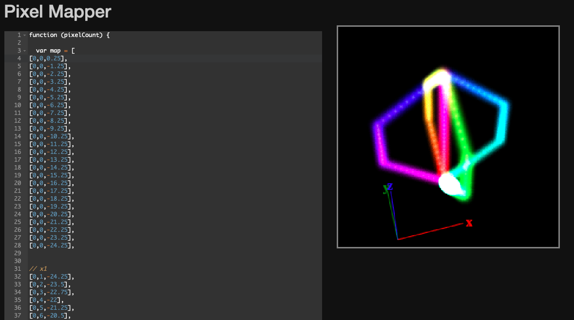
Made it, very simple to understand and implement-if a bit time consuming. I’m sure you could pull it off with a few lines of code but I’m happy that from now on I can do most maps in this manner.

Thanks!

2 Likes

Quite welcome. Yes, it’s a simple concept. Manual, spreadsheet, or code, whatever works. If you want to improve your mapping code skills, this is a good example of easy to code up.

That is super cool, nicely done!

1 Like

Extremely easy to do, added a mode variable and if statements for the individual maps, whenever I need to switch maps it’s one keystroke away:)

For anyone wanting to do the same:

Screen Shot 2021-11-18 at 2.38.28 PM

So if I accidentally press the “load example” button, my saved map is gone, correct? Would it be an idea to add a “custom map” in the list?

1 Like

As long as you don’t press “save” you can reload the page in your browser and it will pull the original code back.

If you want to make certain you don’t lose it, you can download a copy of the mapping function from http://{your_pixelblaze_ip_here}/pixelmap.txt to save somewhere, and if you’ve got access to Python you can do a full backup (patterns, pixelmap, hardware and expander configs) of all your PBs using this script.

2 Likes

wow! that looks awesome!

it would be cool if the map page had a list like patterns, and you could edit/save and select the active map. just a thought. it would be more useful if you could set which map to use on a per pattern basis, or have code in the pattern to switch maps.

2 Likes