Hi @Changchung,
Did you mean the Sensor Expansion board? The Output Expander drives LEDs, but doesn’t have any inputs.
To read a 12V value, you can use the GPIO pins on the underside of PB and/or the analog inputs on the Sensor Expansion board, but the voltage must be reduced first.
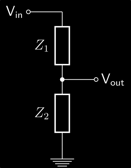
The typical way is to use a voltage divider.
Automotive voltages vary, and are usually higher than “12V” and are upwards of 14.7V when charging, and could be momentarily higher. The signals are also not “clean” and often have some noise.
I would use 10K on the low side, and 40K on the high side. That will give you 3V out with 15V in, and 2.4V out (still high enough to read) with 12V in.
In addition to this, you could add some protection circuitry, such as a diode from the divider output to the 3.3v supply on the sensor board. This would prevent higher voltages from shooting above 3.3v.
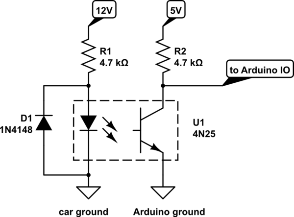
For even better/safer results, use an optoisolator / optocoupler like this (but with 3.3v instead of 5V):