Hi y’all,
I’m trying to set this up properly but have no clue how to connect these components together “in the right manner” any help would be appreciate.
Hi y’all,
I’m trying to set this up properly but have no clue how to connect these components together “in the right manner” any help would be appreciate.
The documentation is a little sparse on the basics, but this will get you started.
You won’t need the multiplexer board on the left to wire up the LED matrix you have shown – it’s for fanning out the signal to 8 data lines and you’ve only got one.
There are some suggestions here for wiring up the sensor board on the right.
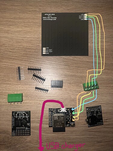
Thank you Pixie really appreciate your time and effort !! Do you have any idea on how to solder the expansion & sensor board on the Pixelblaze?
There’s a picture on the Sensor Board page that might help:
As long as you make sure GND goes to GND, you should be able to choose the orientation you like (above or below; sandwich or lapped wide).
The Pixelblaze and sensor board on that picture got 7 pins and my Pixelblaze v3 got 8 pins and the sensor board 7 pins, It won’t fit
That’s correct! A prior version of Pixelblaze had only 7 pins.
Just line up GND and leave the 8th position disconnected.
This topic was automatically closed 120 days after the last reply. New replies are no longer allowed.