Hey! @wizard and I cowrote this reply for you. I did all the design for a 140K LED art car where many of these issues were relevant.
It’s true! The way it works is it has the three LEDs (RGB) in series, and uses a FET to shunt the colors that aren’t on, so it consumes the same current whether one, two or three elements are enabled at any given time. This means any full-intensity saturated color uses the same current as a full-white LED: 100% red takes the same power as 100% white. 50% red and 75% green would take 75% of max current/power. 12 V strips also waste more power as heat when displaying red vs white.
This is just the way all 12 V strips currently work.
I use max current calculations and know that the end result will be safe but overkill. The last thing I want to be doing is spending time troubleshooting flicker and power injection problems, or worrying about heat burning something up.
For connectors, I trust their rating. More on that below - there are lots of decent high-current options.
Beyond the basics of using an online calculator, here are a few things I do to choose the smallest safe and functional wire gauge:
-
I measure the true max current for my LEDs instead of trusting the specs. For example, the 5V pixel rule of thumb is 60 mA per pixel, but I measured my SK9822’s at 53 mA per pixel. Or, Ray Wu’s 30/m WS2815s say they use 7.2 W/m (20mA per pixel), but I measured it never saw more than 12mA. When lighting an entire long strip at full intensity, I tend to see even less overall draw because the copper traces are adding resistance.
-
I strongly consider planning to run any installation at 70-80% of its max brightness. Due to the way our eyes perceive light (Steven’s power law / gamma correction), this will only appear 10-15% less bright than full power draw, but you save lots of current, thus extending the life of the LEDs, reducing heat, reducing the weight and cost of the copper required, etc. However, you may choose to still spec cables and connectors for max draw because there are scenarios where a bad pixel, data corruption flicker, or misconfiguration can send the strip to something approaching 100% full white.
-
After these two factors, there are good reference tables out there to pick a wire gauge. My go-to is the “Chassis wiring” column in the PowerStream ampacity chart. It’s still conservative, and I’m picking a wire this big because I want to feel good about walking away from my installation and having some failure turn it all-white and still know everything is safe. If I’m just using a strip on my bench for a second? I might go smaller because I know the average draw is almost never full-white. Then you burn a few things a few times in a limited-consequence environment and learn

So, for your 11A through each injection point, I’d pick 18 AWG (rated 16 amps) and feel great about it for safety as long as this isn’t bundled with a bunch of other power wires.
Next, however, you also need to do a voltage drop calculation and make sure you still have something approaching 12 V at the point where the current enters the strip. Let’s say I’m willing to lose 1 V between the power supply and the strip, because I tested my patterns and they all look fine at 11V.
V = I * R
1 = 11 * R
This means I can have up to .09 ohms in that wire. Given the resistance of 18 AWG in that chart (~6 ohms per 1000’), that’s 7 ft between the power supply and LEDs before I lose 1V at full-white draw. Note: it comes out to 14 ft but you have to divide by two because you lose voltage in both the positive and ground wires.
You said 5m to first pixel, so assuming your 11A per injection point is actually correct, then 16AWG will drop less than a volt. If everything is linear though, it’s 5m from power supply to first pixel, but 11m from supply to last pixel. If you want that injection to drop under 1V, you’re very close if using 14AWG.
Again, you need to test, as I suspect you’ll find it difficult to actually draw 11 amps through these. I bet you’ll see a real 5 A max.
I try to respect the max current rating of a connector because you’re really solving for the heat generated in an accidental full-white scenario, and yes, you can actually melt connectors. These are all reasonably priced and can handle a lot of current:
- Anderson Powerpole
- XT60
- Deans
- fully insulated disconnects
- MC4
Sometimes you start to prioritize convenience over price and treat yourself to:
- LLT Mxx twist-locks
- Neutrik powerCON
- WeatherPack
- other fancy automotive ones.
I know a guy who swears by using XLRs as a cheap solution for combined power + signal under 15A.
Experimental results can be helpful here. Try a dubious setup in your home for 30 minutes to find out! It might cost you some money in burnt-up stuff, but it might cost less than over-spec’ing your wire and it’s definitely cheaper than the lawsuit.
If you’re using something like a MeanWell with over-current protection, the supply will shut off or start to drop voltage lower until you see redshift and flicker. The easiest solution is to just set your max brightness: 400W / 550W = 73%. Early in my journey, I was all about melting faces and using max brightness. We all tend to learn this lesson over time but… 73% will be fine. It will be scintillating. Nobody will notice. If you really need it brighter, double the number LEDs you’re using.
Fuses should be burning out when you have a short. You should spec them for just over what you’ll expect to draw during your most intense normal operation. Related, you said above:
Fuse protection is a must, and tricky with high current and long wire runs! Usually drawing too much power via LEDs isn’t going to cause a fire unless your power lines or connectors are resistive in one concentrated spot, but a short can melt everything if given enough power.
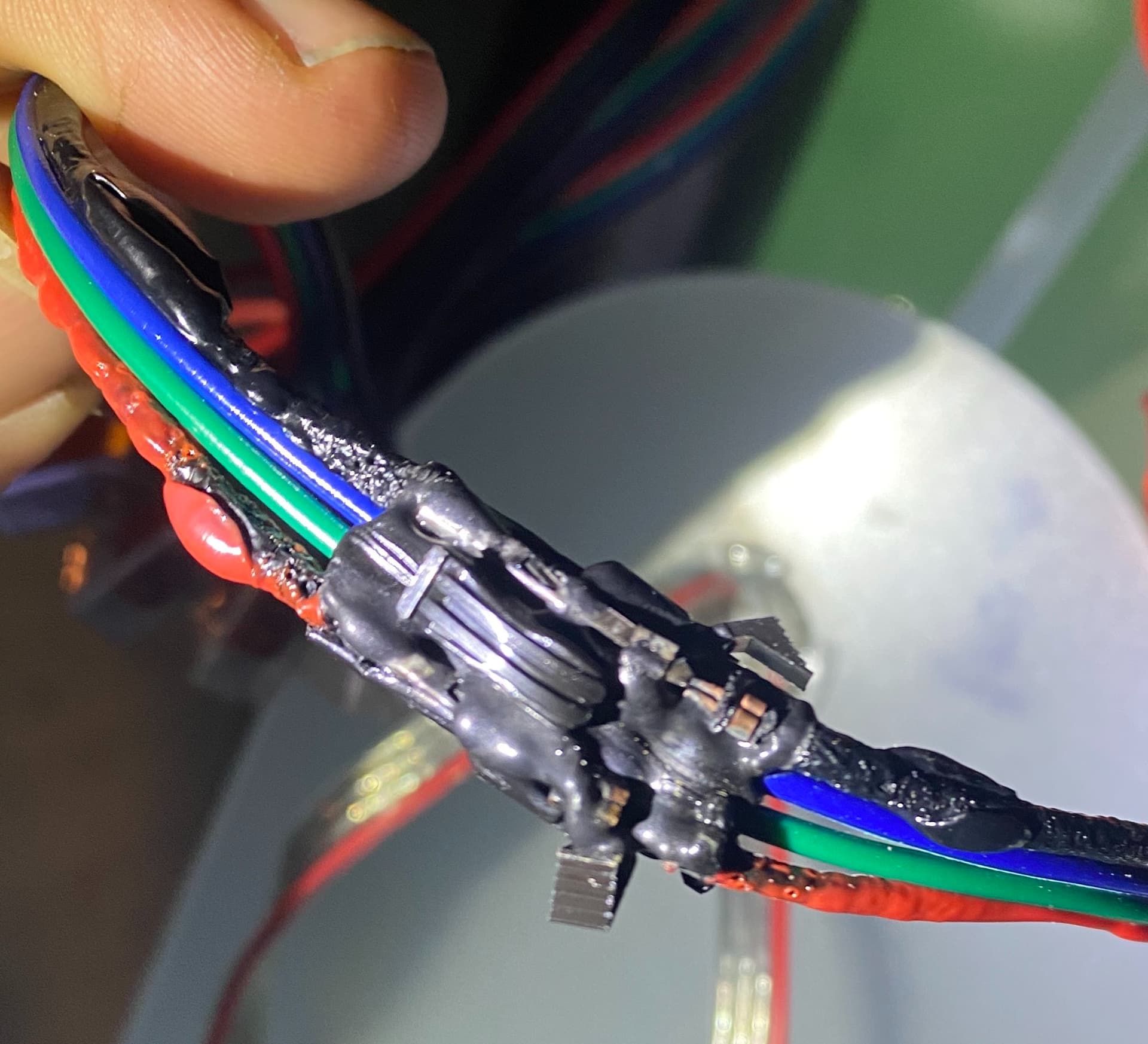
Hey look, it’s a JST-SM rated for 3A per contact and my fuse didn’t blow.
Most power supplies have some short protection, but only if the current consumed exceeds what they can output; long wires, connector contacts, and strips all have resistance and can prevent this protection from triggering.
I feel like the whole “ghost pixel” (signal booster) thing is really a leftover from crappy WS2811 LEDs people put on their homes for Christmas lights. It’s a marginal solution at best. When your data to first pixel is being corrupted by wire length, use a differential transceiver.
I don’t think running data next to your ground is an issue. Many times you’ll find a slight improvement by using twisted pair (like an ethernet cable) to twist your data right next to the ground intentionally. I suspect that with 18 AWG, a 5m distance to the first pixel is reasonable, but 864 LEDs in a row is a lot to propagate signal correctly. You’ll find that increasing distance to first pixel means that signal-related flicker will creep forward in a long run: In other words, maybe 5m works fine for the first 400 pixels, but you shorten to 3m and find all 884 working.
Pixel manufacturing batches can vary - when you’re on the margin like this, distance to first pixel is something you’ll need to test.
I like designing fixtures that put the controller as close to the first pixel as possible. With Pixelblaze and the Pico being so small, it’s never been easier. On some 12 V installs, I have the Pixelblaze powered by a minibuck and hanging off a short pigtail a few inches off the first pixel so I can tuck it away. Rainproofing is covered in several other threads here.
If controlling power via max brightness isn’t desirable, you might consider modifying each pattern individually. It’s more work, but would let you get the most from each pattern while controlling power.
The general approach is to calculate all your pixels in beforeRender, store their intensities in an array, and then calculate an attenuation factor that only kicks in when your overall draw is over your limit.
There are two examples in this topic of writing code to maximize per-LED draw while staying under some overall limit. You’ll want to look at the second example (mine) because it’s more applicable to how 12V current draw works across colors as explained above.