Wiring multiple LED strips

Hey @Mebejedi! In your diagram, power supply 2 transmits power both ways, IE to the second and third strip.

By “booster”, I think you are referring to “data boosters”, AKA signal amplifiers AKA null pixels (and not some kind of power booster product); when we want to re-boost the voltage I usually just call that as power injection.

I’ve never used the data booster things, but I think the concept is that they take degraded 5V data and restore it to a cleaner 5V digital signal.

Since apparently it’s recommended to use them every 10M, I assume you’re thinking of putting the booser between strands 2 and 3, where the A and B is labeled. In this case, although power is flowing both directions, the dirtiest signal is at the end of strand 2, and it’s clean again on the DIN side of strand 3. This should probably work. The data booster itself would be powered at the injection point in your diagram and consumes very little power. In your setup, if you were boosting signal between strands 1 and 2, you’d power the booster by tying its power-in side to either strand, but NOT both.

Therefore, a data booster at the end of a run of strands doesn’t do anything (but power injection is common at the end of a run).

I would insulate any power lines that have exposed metal conductor. If it’s pre-stripped injection wires, yeah, snip them or use electrical tape. If it’s female barrel connector or female JST-SM I typically leave them exposed. On most power supplies, the terminal block screws are well isolated and don’t need too much extra protection.

Sorry, yes. That’s what I meant…power injection. And it does look like it goes both ways.

Unfortunately, I have intermittent problems with my Pixelblaze losing its wifi settings, and it won’t switch back over to my home network. Kind of annoying.

That’s strange. You don’t have an external button wired up, do you? What firmware revision is it running? I seem to recall more WiFi setup issues on older firmware, but for the most part if I set it to join a network it stays on it. Now, glitching when the WiFi is weak - that’s a much more common problem for me.

Well, I’m using these connectors…

And I noticed when I trusted them against each other, the orange light on the PB would start flashing and it would connect. Some other threads in here talked about how a poor power supply or connection could affect the wifi, so I guess that was it.

Now I have another question: what’s a good way to mount or cover this power supply for outdoor wiring? Like on the backside of my eaves?

Maybe I can get some planning advice from you guys. This is the run I’m planning.

I’ll probably have the PB and first power supply on the left side of the house, and try to insert a power injector at points B and C. Is there anything I should plan for or be aware of?

Hi @Mebejedi,
One thing I see with your power injection setup here:
power distribution split segments

I’ve added power quality gradients, basically distance from power. Parts of the strip farther away from a solid power source may have lower voltages than those close to power, which is caused by voltage drop. Voltage drop is caused by resistance, and will change with current draw.

It’s possible for them to swing differently than each other, causing issues with data, and glitches, especially at higher current setups or with longer runs.

When joining 2 power zones, it’s best to inject power to the end and start pixel so they are both near their respective 5V power supply levels.

That also applies to Pixelblaze itself, you don’t want to power it at the far end of a strip away from the power source.

Thats not to say you will have data issues, but its worth testing before you commit to an install.

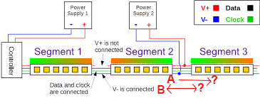
Also, keep in mind if you have the same power supply, you can keep the V+ lines connected. It may be easier to run wire in parallel with your strips and tap in every strip or two.

I’m not a complete noob at electrical wiring, but how would you wire this up?

This is my first year doing this stuff too, but I’m trying some somewhat generously sized outdoor waterproof boxes with adapter plates for my power supplies. I’m ordering them from HolidayCoro.com; this is my first time using them so no record one way or the other for you yet. I’m using their HC-2500 box with base plate predrilled for Meanwell LRS-350W series (up to 4 PS with a tight fit). I’m doing this because I want to put PB and peripherals (e.g. relays / MOSFETs) in the box. Other people will just wire directly to a waterproof supple like the Meanwell LPV/HLG series or popular budget waterproof supplies.

Regarding:

For power injection techniques, there seem to be quite a few. If you don’t mind using Facebook (:expressionless: ) the LEDs Are Awesome group has many posts about different techniques (like this one).

A few ways I’ve done this: zip tie large gauge copper wire to the back (you should size up by 2 AWG if using the budget copper-clad aluminum “CCA”). Look for some videos on a technique called “window stripping electrical wire” to solder tap in with minimal extra width, or get a quick automatic wire stripper with a strip length stop for speed and consistency and use Wago 221s. If you window strip, don’t forget planning for your heat shrink on the correct side (or use electrical tape).

So, I was actually thinking of wiring my lights like the top diagram with my 300W power supply, and then was lucky enough to run across this picture that demonstrated it.

My question is this: Could I also do it like the bottom diagram with the PB? Or would this require the expansion board as well?

The bottom diagram is pretty much what the expansion board is for. Do be thoughtful about current, though, as that diagram seems more appropriate to some of the driver boards that are meant for larger power distribution.

The output expander can deliver 3A, and the pro version can do 15A.

For several projects I have wired both power and data in a star pattern using the output expanders, but if using over 150 pixels total with the normal expander (750 on the Pro), make sure +5V and GND power is separately delivered through appropriate size wire, not through the expander.

1 Like

So, this box has predrilled holes that line up with your power supply? That’s kinda nice. I’m trying to figure out how to mount mine inside the box.

For your outdoor lights, How far from your LEDs is your power supply and PB? I’m debating if I should mount those inside my garage, and run about 10ft lines to the strip.

(FWIW, tomorrow, I’ll be running 25+ feet of data line from the expansion board in my main control box to the upstairs balcony roofline. The lights are up and that section has its own power supply, so it’s just data and common ground. I’ve got several things to try, from shielded wire to a fake null pixel mid-run. Will post results after the experiment.)

1 Like

After a near catastrophe involving two connectors that looked identical but were wired very differently, I got the balcony working. (thought I’d put all those in a separate bin. just one more good reminder to check voltages and polarity before powering up Pixelblaze or lights.)

The line was actually longer than I thought. It worked the first time out – didn’t need any of my planned trickery to get it to work. It took about 30 feet of leftover 2-conductor 22 ga. low voltage outdoor lighting wire.

The wire pic shows the data line run after I connected it for testing, before I mounted it (under that flashing.) Everything shown lit is controlled by one pixelblaze+oe. The box is mounted under the balcony near the far left pillar, and each level has its own power. Even good pictures don’t do justice to how good these lights look on a house!


5 Likes

That looks really sweet!

Did you use 22g for the power, or data (are they two separate things?)

All the wiring in the system is about the same size. That particular long data run is the only place where I needed to totally separate power and data. Most of it’s done w/4 conductor wire, but upstairs the power box was very close to the strip, and the controller was quite far away. It was easiest to run two sets of wires.

I’m running two 120w power supplies, one in the main control box, and the other in a power box on the far end of the upstairs balcony. There are a couple more 10 foot sections of lights still to add (tomorrow, I hope!) downstairs, but so far it doesn’t seem to need additional power injection.

What has really surprised me is how good it looks. Not just burningman@home cool, but actually really good. It makes the house better! Also, it can throw enough light on the entire yard that you could have a party out there when we get back to being able to have parties. I think you’ll really enjoy it when you get yours finished!

2 Likes

Good news: The wiring and hardware works.

Bad news: my mounting system did not.

But, I’d rather have this situation than the opposite, lol. I’ll work on it some more tomorrow.


1 Like

That’s going to look great when you get it done! House projects are famous for taking way more time and work than planned for. All part of the joy of home ownership.

Just keep going 'till you get it the way you want it. It’s worth some experimentation. I spent a couple of weeks playing with mounting methods 'till I found one that worked, was robust, and looked reasonably decent.

Yeah, zip-tying the strips to the PVC worked well, but the clips are difficult to work with. I’m going to look for screw-in ceiling hooks at Lowes tomorrow.

I was really tempted to try it under the eaves like your house. What kind of strips are you using? They look more like bulbs.

Mine are individual WS2812 pixels on a strand, specifically made for outdoor mounting, with waterproof connectors, heavy plastic casing for the individual LEDs, and other features to increase durability. The only downside is the zillion tiny, fairly precise holes that had to be drilled to make it work.

They’re mounted behind 3/4" radius steel drywall corner bead, which amounts to a 10 foot piece of thin 3/4" steel half tube with handy mounting flanges on either side. It stacks well so I was able to save hole drilling time by stacking, clamping and drilling several at once. I then pre-painted, installed the LEDs and mounted each section with 3 small construction screws – one at each end and one in the middle. They’re rock solid, and nearly invisible in the day.

2 Likes