3D Maping Rhombic Dodecahedron & More

Hello people,

First time user here. After messing around with SP107/SP108’s I have decided to look into some real LED control and have ordered a few PB V3’s. I feel like going directly down the Arduino route would be a pretty steep learning curve and PB seems like a happy medium.

280px-Rhombicdodecahedron

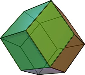
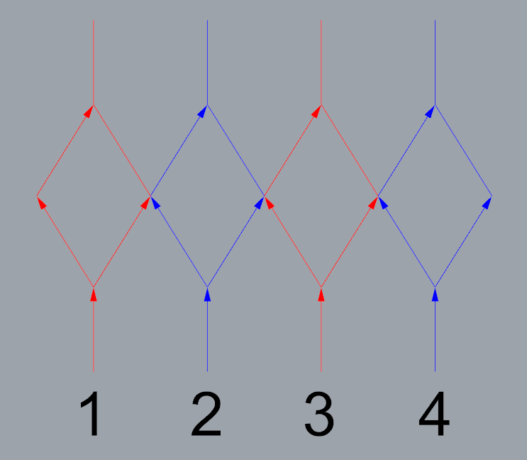
My project is an infinity mirror rhombic dodecahedron, using WS2812b’s (60 p/m) which I intend on bumping up to higher densities in versions to follow. Currently it is using a single data input, mirrored 4 ways with 1 fork or split per line. Colours on the diagram are for clarity. I know that swapping to a mapped system requires a completely different strip configuration and plan on tweaking my design to suit.

A couple clips running on a Sp107e.

Yes, I have seen the Adam Savage one day build. I will be using a similar if not exact copy of the wiring scheme they ended up using. I am open to any ideas on this too.

My questions are:

  1. How would I go about mapping this object? Will I be manually plotting pixels or vertices/edges? (I can use my cad files to get x,y,z point data for each pixel in sequence).

  2. Would changing pixel density require complete re-mapping or is that an adjustable variable?

  3. How difficult is it to adjust premade effects to work on a custom 3D map? will I be making them from scratch every time? I feel like my current LED sequence would give better ‘plug and play’ results with 1D effects but taking the time to map it correctly would be unmatched.

Im sure having the PB unit and software in hand will help with understanding how to move forward, I just wanted to get an idea of what I’ll be doing so that I can hit the ground running once everything turns up.

Thanks in advance.

(Edited for formatting)

Pixels.

It’s a remap but it depends on how you built your map. If you just input a series of points, it’ll be a complete remapping. If you use a formula/code to figure out the map, based on X number of pixels per line, then you could alter X, and the remap would be trivial.

What you put into the map section is either a literal array of points, or actual JavaScript code that generates and returns an array of points (it runs once, not dynamically, and it’s run in the browser, not on the PB itself, so you get the full JS language), one set per pixel in order of their pixel order.

Then it’s renormalized into decimal values for each axis, from 0 to 1… So you might want to use math and calculate your points using negative values for half the items (so zero,zero,zero is the very center), and that’s fine… PB will adjust whatever you give it so all values flow 0…1 (so your lowest value becomes 0, highest value becomes 1, the rest are relatively laid out between.)

Super Easy, Barely an Inconvenience.

Not all effects have 3D maps. But if you have a 3D map, then anything with a map (2d or 3d) just “works”. There aren’t many 1D maps yet, most 1D effects just use pixel indexing. Hopefully that will be improved. (There are advantages to each method, and sometimes the same effect done the other way looks different depending on the length/etc)

Welcome to the PB club!

We did discuss mapping of this sort recently, so search the archives for quite a few discussions.

Thanks for the reply, a lot of good info there. Just so I understand the method, what is the purpose behind placing 0,0,0 in the center of the model? In my head it would make for a cleaner set of point data but because of the ‘redistribution’ between 0 and 1 it seems like there would be no difference as to where 0,0,0 is.

Ill keep poking around the forum to find some examples of mapping.

So if you think about a polyhedron as an object, all of the vertexes have regular mathematical points in space. For instance, consider a cube… You could say that one corner was 0,0,0, and the farthest corner from that is 1,1,1… And the other corners would be 1,1,0 etc…

But once you get into a dodeca or other figure, most of those values aren’t integers. But if you place the polygons with 0,0,0 as the center, half of your vertexes align with positive values and the other half mirror with negative ones… And values like the square root of 5 appear… And it’s much easier to manage. In fact, in most cases of regular polyhedra, it’s easy to look up the vertex and often, it’s zero centered.

Once you have the vertexes, it’s trivial to generate the edges: Given 2 points in space, and X pixels between then, you just calculate X spots between the 2. So if you have 10 pixels but then decide to do 20 instead, simple enough to recalc.

The renormalized values from 0…1 per axis are an attempt by PB to avoid worrying about whatever format you used for numbers… Maybe it’s negatives and positives, maybe it’s angles (0-360), etc. The map remains consistent, and a given range no matter what, your Xs will be 0…1, your Y will be 0…1, your Z (if any) will be 0…1…

It’s actually quite a brilliant way to store it. It avoids worrying about overflows or having to scale it in a pattern.

1 Like

Can confirm the vertexes are integers. Does this mean once I have labeled said vertexes (allowing me to track signal travel AB, BC, CD etc) I can have the code evenly distribute pixel locations between said points? and if so what would code for something like that look like? keep in mind I can barely construct coherent sentences let alone code.

If i can avoid getting X,Y,Z data for potentially 500+ nodes that would be great.

Made in Rhino5

See this is why you can look it up:

The eight vertices where three faces meet at their obtuse angles have Cartesian coordinates

(±1, ±1, ±1)

The coordinates of the six vertices where four faces meet at their acute angles are:

(±2, 0, 0), (0, ±2, 0) and (0, 0, ±2)

Which is equivalent to your model divided by 2…

So code to calculate X points between two given vertexes is pretty easy. I’ve been meaning to write a generic poly mapper, and will do so in the next few days. That will solve your need as well as anyone else in the future. I’m thinking for PB purposes, the easiest is to give it a list of paired vertexes, so if you jump around wire wise, it is easy to edit that list.

Bringing this one back to life, have you had any advancements on a poly mapper?

Given the Transformation API, which let’s you do rotation and scaling, and that you can enter any coordinates you wish, not sure what else is needed.

Use any known polygon creation software you like to figure out coordinates, or write your own math code, and it should just work.

I promised a generic “vertex to vertex” mapper above but No, I haven’t written that, it’s pretty trivial though (given Ax,Ay and Bx, By, and N number of points between them [non inclusive of A and B], each point is some 1/N coordinate between the two)

Sadly still not in headspace/energy to write it up, but I’ll add it back to the Todo list, I guess.

First attempt. N is the number of divisions not the pixel count, should be easy to change if I feel the need. Either way you end up with the same result.

function (pixelCount) {
  
  var N = 9

  function line(Ax, Ay, Az, Bx, By, Bz, N) {
    
    var dx = (Bx - Ax) / N;
    var dy = (By - Ay) / N;
    var dz = (Bz - Az) / N;
    
    var line = [];
    for (var i = 1; i < N; i++) {
      line.push([Ax + i*dx, Ay + i*dy, Az + i*dz]);
    }
    return line;
  }
  
  var map = [];
  
  map = map.concat(line(0, 0, 0, 0, 1, 0, N))
  map = map.concat(line(0, 1, 0, 1, 1, 0, N))
  map = map.concat(line(1, 1, 0, 1, 0, 0, N))
  map = map.concat(line(1, 0, 0, 1, 0, 1, N))
  map = map.concat(line(1, 0, 1, 1, 1, 1, N))
  map = map.concat(line(1, 1, 1, 0, 1, 1, N))
  map = map.concat(line(0, 1, 1, 0, 0, 1, N))
  map = map.concat(line(0, 0, 1, 0, 0, 0, N))
  
  return map;
}

I will drop back in later with my actual map(s). This is going to be an insane time saver :slight_smile:

2 Likes

So that does include A but not B’s point, if you want it to include B (you might in some cases), then you need to loop to the full N.

Edit: oops, no A either, see below

Ideally I would want to exclude both end points (A & B), how would you go about doing that? I’m still in the early stages of understanding formulas/javascript. Monkey see, monkey do.

edit: spelling

Oh, my bad, you set i to 1 to start, so you are skipping A also. (Basically i=0 is A, i=N is B)

But the reason I misread, is in your case, you likely do want A but not B… Because you’re doing
Sequential segments, when each B becomes the next A.

Here’s it with an actual set of points. I’m getting the ‘empty’ corners/vertices I was looking for, though there seems to be slight offset. Functions flawlessly on my test rig.

function (pixelCount) {
  
  var N = 8
  

  function line(Ax, Ay, Az, Bx, By, Bz, N) {
    
    var dx = (Bx - Ax) / N;
    var dy = (By - Ay) / N;
    var dz = (Bz - Az) / N;
    
    var line = [];
    for (var i = 1; i < N; i++) {
      line.push([Ax + i*dx, Ay + i*dy, Az + i*dz]);
    }
    return line;
  }
  
  var map = [];
  
  // Segment 1.
  //A -> B
  map = map.concat(line(-0.000,-61.803,-80.902,-58.779,-19.098,-80.902, N))
  //B -> J
  map = map.concat(line(-58.779,-19.098,-80.902,-95.106,-30.902,-19.098, N))
  //J -> K
  map = map.concat(line(-95.106,-30.902,-19.098,-95.106,30.902,19.098, N))
  //K -> S
  map = map.concat(line(-95.106,30.902,19.098,-58.779,19.098,80.902, N))
  //S -> R
  map = map.concat(line(-58.779,19.098,80.902,-36.327,-50.000,80.902, N))
  //I -> J
  map = map.concat(line(-58.779,-80.902,19.098,-95.106,-30.902,-19.098, N))
  
  // Segment 2.
  //B -> C
  map = map.concat(line(-58.779,-19.098,-80.902,-36.327,50.000,-80.902, N))
  //C -> L
  map = map.concat(line(-36.327,50.000,-80.902,-58.779,80.902,-19.098, N))
  //L -> M
  map = map.concat(line(-58.779,80.902,-19.098,0.000,100.000,19.098, N))
  //M -> T
  map = map.concat(line(0.000,100.000,19.098,0.000,61.803,80.902, N))
  //T -> S
  map = map.concat(line(0.000,61.803,80.902,-58.779,19.098,80.902, N))
  //K -> L
  map = map.concat(line(-95.106,30.902,19.098,-58.779,80.902,-19.098, N))
  
  // Segment 3.
  //C -> D
  map = map.concat(line(-36.327,50.000,-80.902,36.327,50.000,-80.902, N))
  //D -> N
  map = map.concat(line(36.327,50.000,-80.902,58.779,80.902,-19.098, N))
  //N -> O
  map = map.concat(line(58.779,80.902,-19.098,95.106,30.902,19.098, N))
  //O -> P
  map = map.concat(line(95.106,30.902,19.098,58.779,19.098,80.902, N))
  //P -> T
  map = map.concat(line(58.779,19.098,80.902,0.000,61.803,80.902, N))
  //M -> N
  map = map.concat(line(0.000,100.000,19.098,58.779,80.902,-19.098, N))

  // Segment 4.
  //D -> E
  map = map.concat(line(36.327,50.000,-80.902,58.779,-19.098,-80.902, N))
  //E -> F
  map = map.concat(line(58.779,-19.098,-80.902,95.106,-30.902,-19.098, N))
  //F -> G
  map = map.concat(line(95.106,-30.902,-19.098,58.779,-80.902,19.098, N))
  //G -> Q
  map = map.concat(line(58.779,-80.902,19.098,36.327,-50.000,80.902, N))
  //Q -> P
  map = map.concat(line(36.327,-50.000,80.902,58.779,19.098,80.902, N))
  //O -> F
  map = map.concat(line(95.106,30.902,19.098,95.106,-30.902,-19.098, N))
  
  // Segment 5.
  //E -> A
  map = map.concat(line(58.779,-19.098,-80.902,-0.000,-61.803,-80.902, N))
  //A -> H
  map = map.concat(line(-0.000,-61.803,-80.902,-0.000,-100.000,-19.098, N))
  //H -> I
  map = map.concat(line(-0.000,-100.000,-19.098,-58.779,-80.902,19.098, N))
  //I -> R
  map = map.concat(line(-58.779,-80.902,19.098,-36.327,-50.000,80.902 , N))
  //R -> Q
  map = map.concat(line(-36.327,-50.000,80.902,36.327,-50.000,80.902, N))
  //G -> H
  map = map.concat(line(58.779,-80.902,19.098,-0.000,-100.000,-19.098, N))
  
  return map;
}


Given those values, I suspect your slight offset might be due to multiplying/dividing precision. Try multiplying everything by 10 or 100, and see if it improves. It’s all renormalized in the end, anyway.