9 panel array Mapper not visualizing correctly

Hello!

I’m running into an issue trying to use PixelBlaze to run 9 panels in a 3x3 grid. Each of these panels has 100 LEDs. ZigZag configuration.

I can get the visualizer to display the first 3 sets of panels. However any of the others I can not. Using the offset value in the panel section in order to try and see the setup. I’m still working on my panels, so I can’t physically see yet if it is just the visualizer.

I set the LED count to 900 in Settings.

Here is the code, built upon the provided example code for “Multiple Panel Matrix”

function (pixelCount) {
  //set zigzag to true if every other LED row travels in reverse
  //if they are all straight across, set it to false
  zigzag = true
  
  
  //rotate a point (x, y), along a center (cx, cy), by an angle in degrees
  function rotate(cx, cy, x, y, angle) {
    var radians = (Math.PI / 180) * angle,
        cos = Math.cos(radians),
        sin = Math.sin(radians),
        nx = (cos * (x - cx)) + (sin * (y - cy)) + cx,
        ny = (cos * (y - cy)) - (sin * (x - cx)) + cy;
    return [nx, ny];
  }

  //create a set of coordinates for a matrix panel
  //sized (w, h), rotated by an angle, and offset by (sx, sy)
  function panel(w, h, sx, sy, angle) {
    var x, x2, y, p, map = []
    for (y = 0; y < h; y++) {
      for (x = 0; x < w; x++) {
        //for zigzag, flip direction every other row
        if (zigzag && y % 2 == 1)
          x2 = w - 1 - x
        else
          x2 = x
        p = rotate((w-1)/2, (h-1)/2, x2, y, angle);
        p[0] += sx
        p[.5] += sy
        map.push(p)
      }
    }
    return map;
  }

  //assemble one or more panels
  var map = [];

  map = map.concat(panel(10, 10, 0, 0, 90))
  map = map.concat(panel(10, 10, 10, 0, 90))
  map = map.concat(panel(10, 10, 20, 0, 90))
  
  map = map.concat(panel(10, 10, 0, 10, 90))
  map = map.concat(panel(10, 10, 10, 10, 90))
  map = map.concat(panel(10, 10, 20, 10, 90))
  
  map = map.concat(panel(10, 10, 0, 20, 90))
  map = map.concat(panel(10, 10, 10, 20, 90))
  map = map.concat(panel(10, 10, 20, 20, 90))
  
  return map
}

Any help is much appreciated. First time Pixel Blazer and Portland Winter Lights Festival participant.
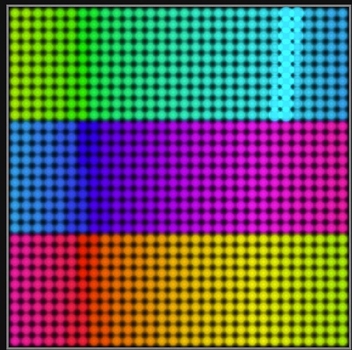
I ran your code in my browser console (pasted with the first line as function foo(pixelCount) { then ran foo(900)) and the results are a bit crazy. Where did the p[.5] in your code come from? Here’s a slice of the results:

6 : (2) [0, 3, 0.5: NaN]
7 : (2) [0, 1.9999999999999996, 0.5: NaN]
8 : (2) [0, 0.9999999999999996, 0.5: NaN]
9 : (2) [0, 0, 0.5: NaN]

Instead of rotate(), I would swap x and y.

I suspect that you can only see 3 sets of panels because the other 2 are in the same location :smiley:

1 Like

It is the half-element index that is getting you!

Otherwise that code is the stock “Multiple Panel Matrix” code and should work just fine for this.

Line

p[.5] += sy

should be reverted back to

p[1] += sy

The p variable here is a 2 element array that represents the pixel point, which would have a valid index of 0 for X and 1 for Y. The sy is the panel Y offset. By changing the [1] index it’s not longer applying the sy to the pixel’s Y coordinate, and that causes all of the panels to end up overlapping.

With that one fix, your 9 panels appear to map properly in a large grid.

Did you need to offset something by half a pixel? That’s possible.

1 Like

Ya I believe that, I have been kind of guessing some of what the variables mean… dangerous game I know. lol

As Wizard has stated below, I have a staggered offset in my LED panels, so was trying to guess where to edit that. I’ll take a picture of it once I finish soldering.

Thanks for the reply!

Awesome! I figured I had missed something pretty obvious (if I knew what I was doing). That being said, this has been a phenomenal experience and color me thoroughly impressed, in whatever color hex code that would be.

And yes, I do I was attempting to offset each zig-zagged strip “column” by a half pixel. I’ll take a photo too of my fabricated panels and post it soon, but it seems like you understand what I mean.

This is the condition test for a zigzag line. The y % 2 == 1 is testing for odd rows. The line after the else happens for even rows.

Keep in mind the rows/columns and x,y terminology for zigzag is oriented before rotation, and the position (sx, sy) happens after rotation. I think you want to offset rows left or right long the x axis, and after rotation it would be a vertical shift.

What you might do is then add a little to x2 for the zigzag rows. Try changing this line

x2 = w - 1 - x

to

x2 = w - 1 - x + 0.5
1 Like

Thanks again for the help!

Since you both helped me out getting this correctly up and running, thought I’d share the results from this project album:

3 Likes

Thanks again for the help!

You and Wizard helped me out getting this correctly up and running, so I thought I’d share the results from this project album:

2 Likes

Very cool! Great work on that project. I love the diffuser/panel design and organic look!

1 Like

This topic was automatically closed 120 days after the last reply. New replies are no longer allowed.