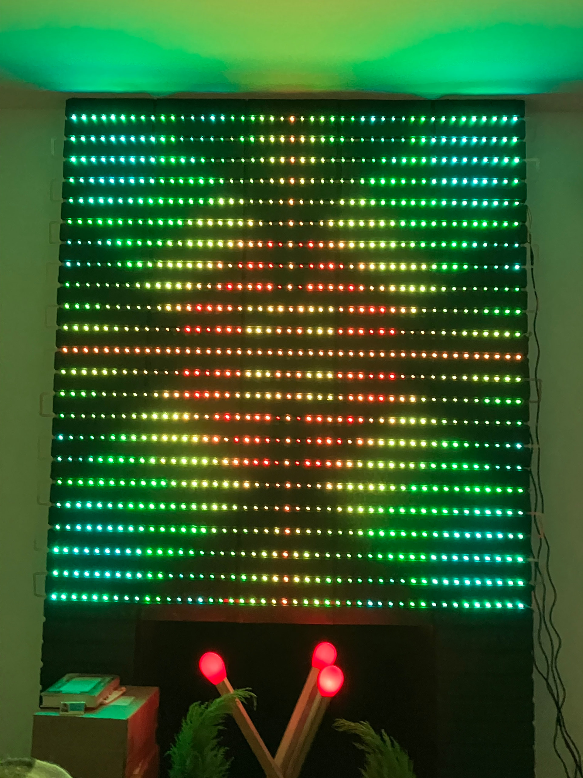
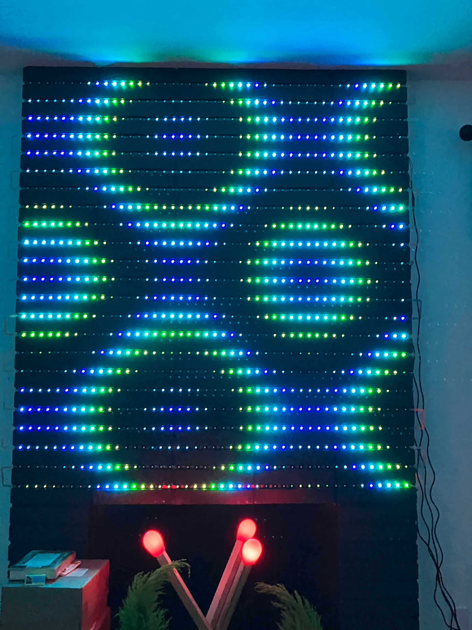
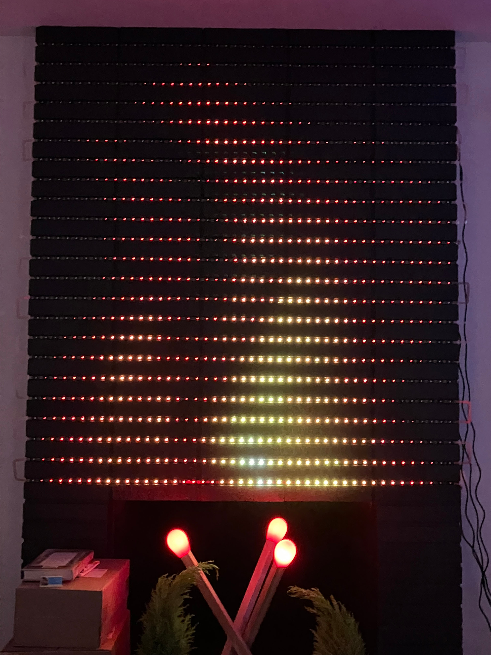
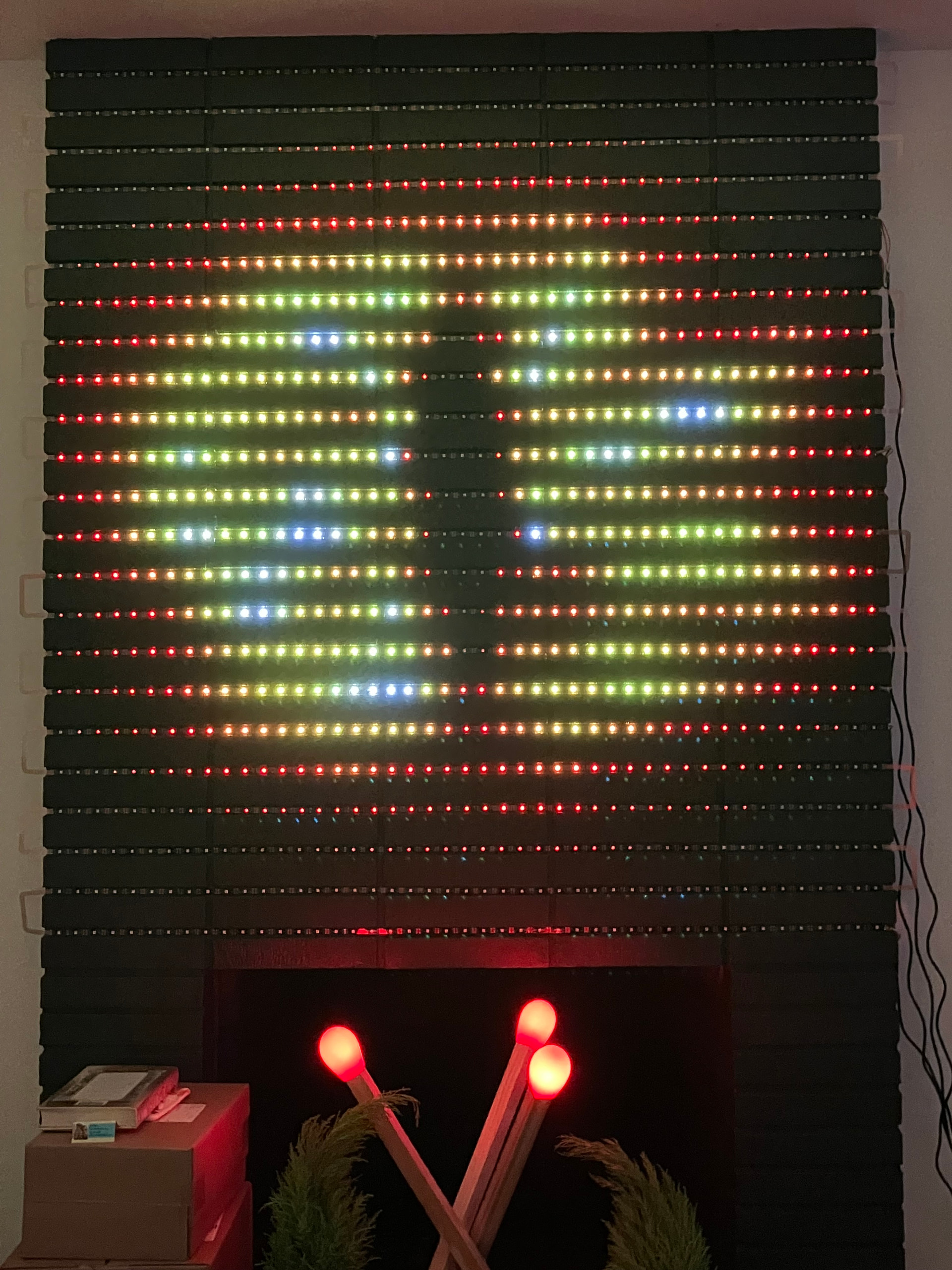
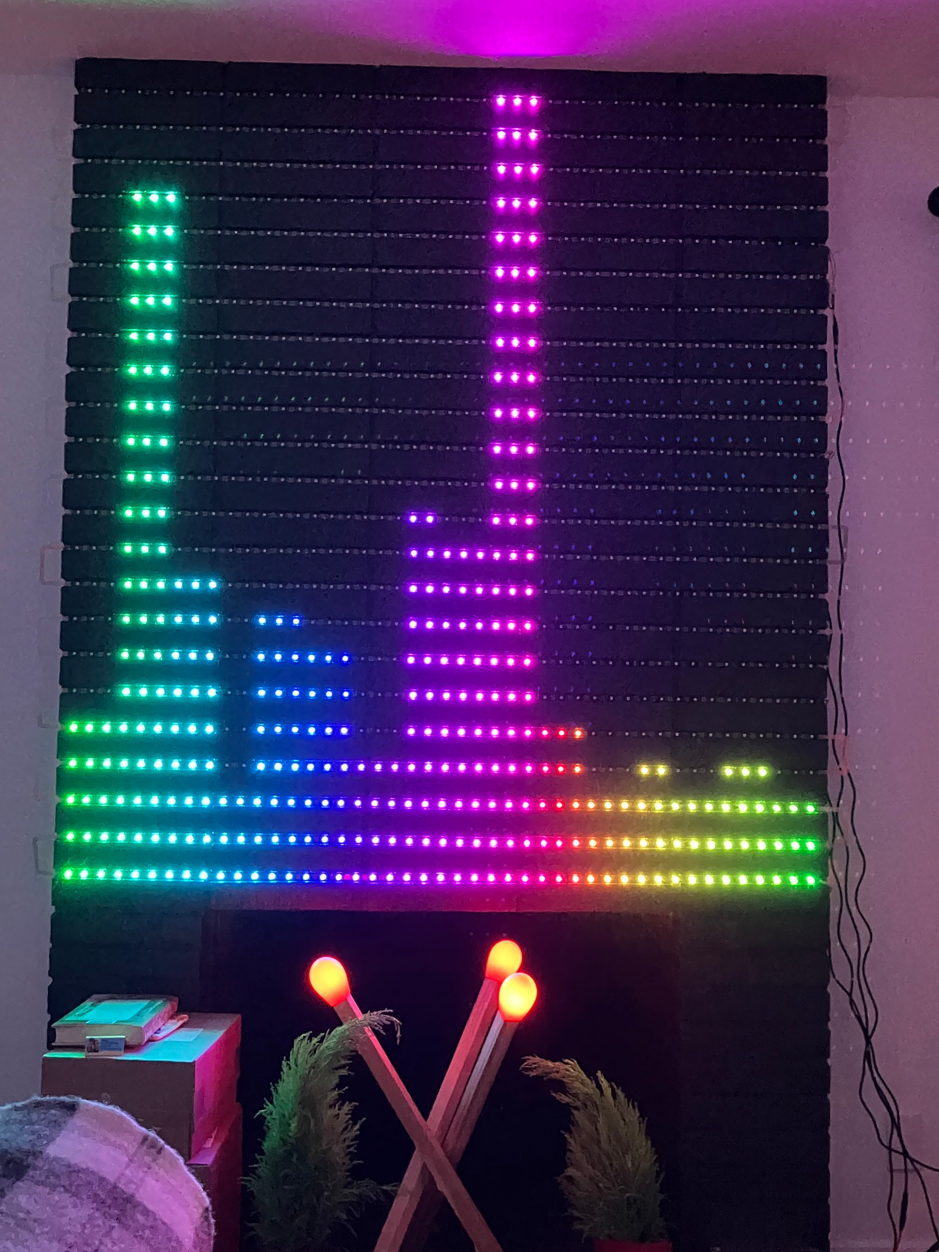
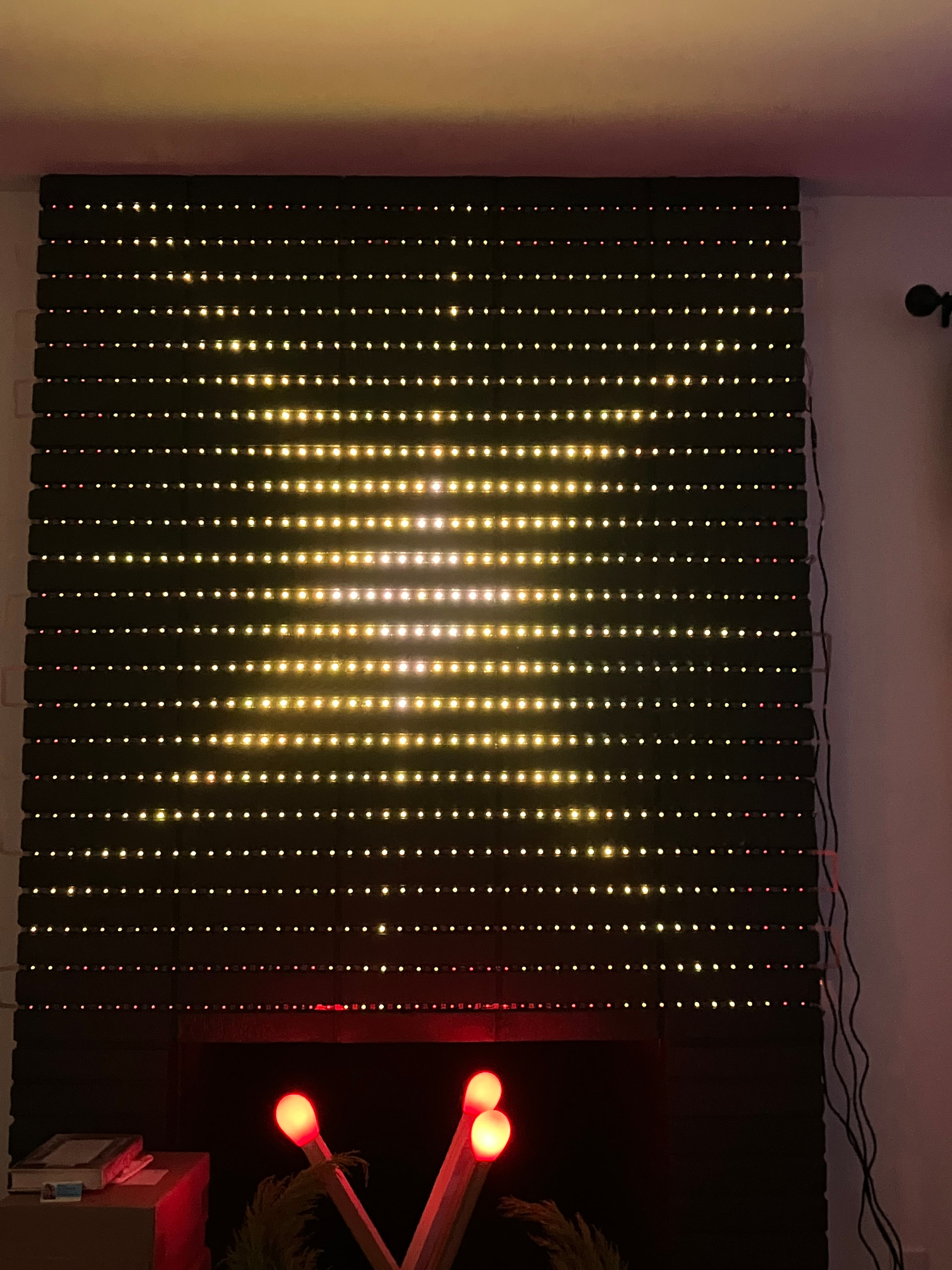
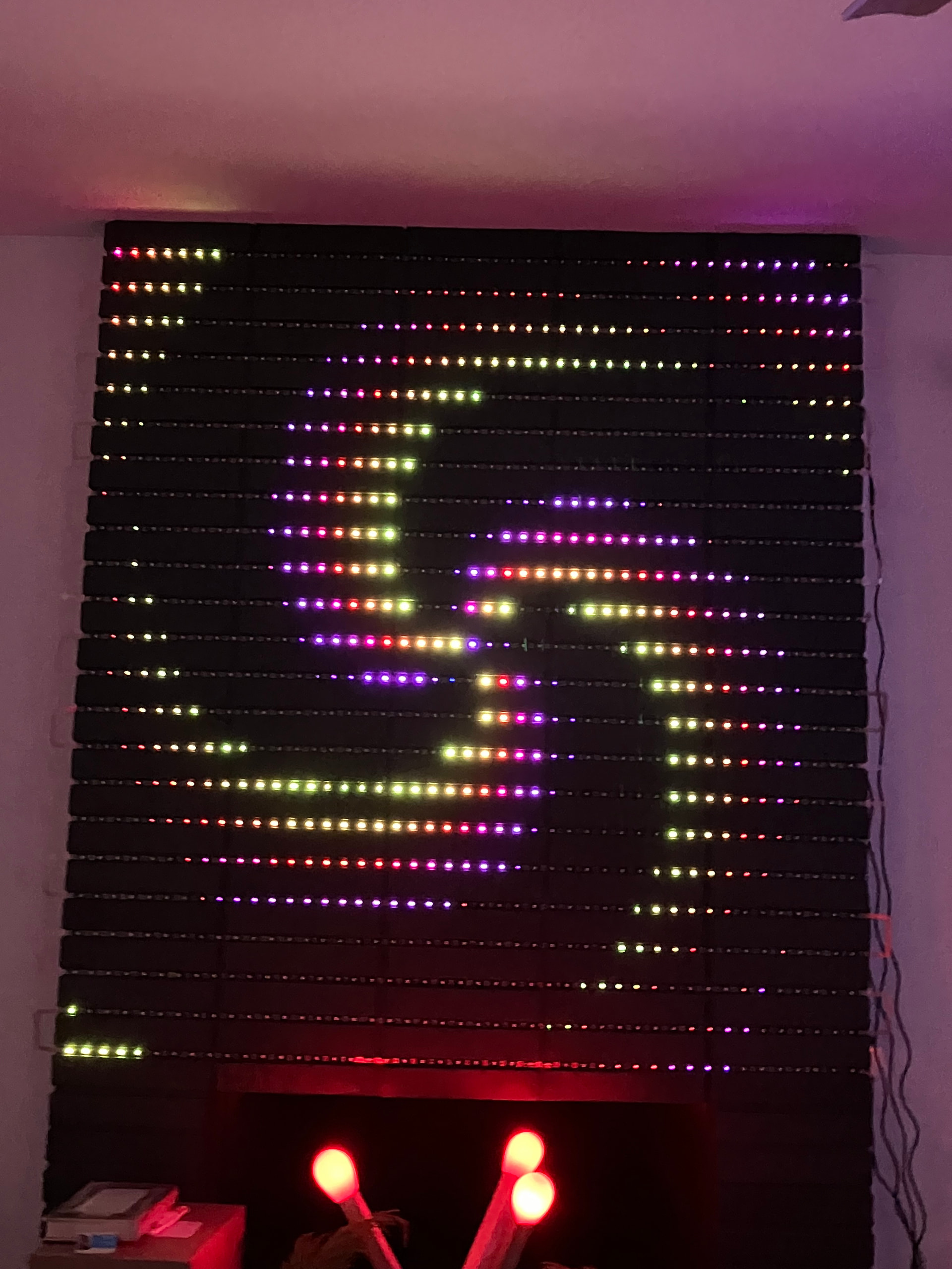
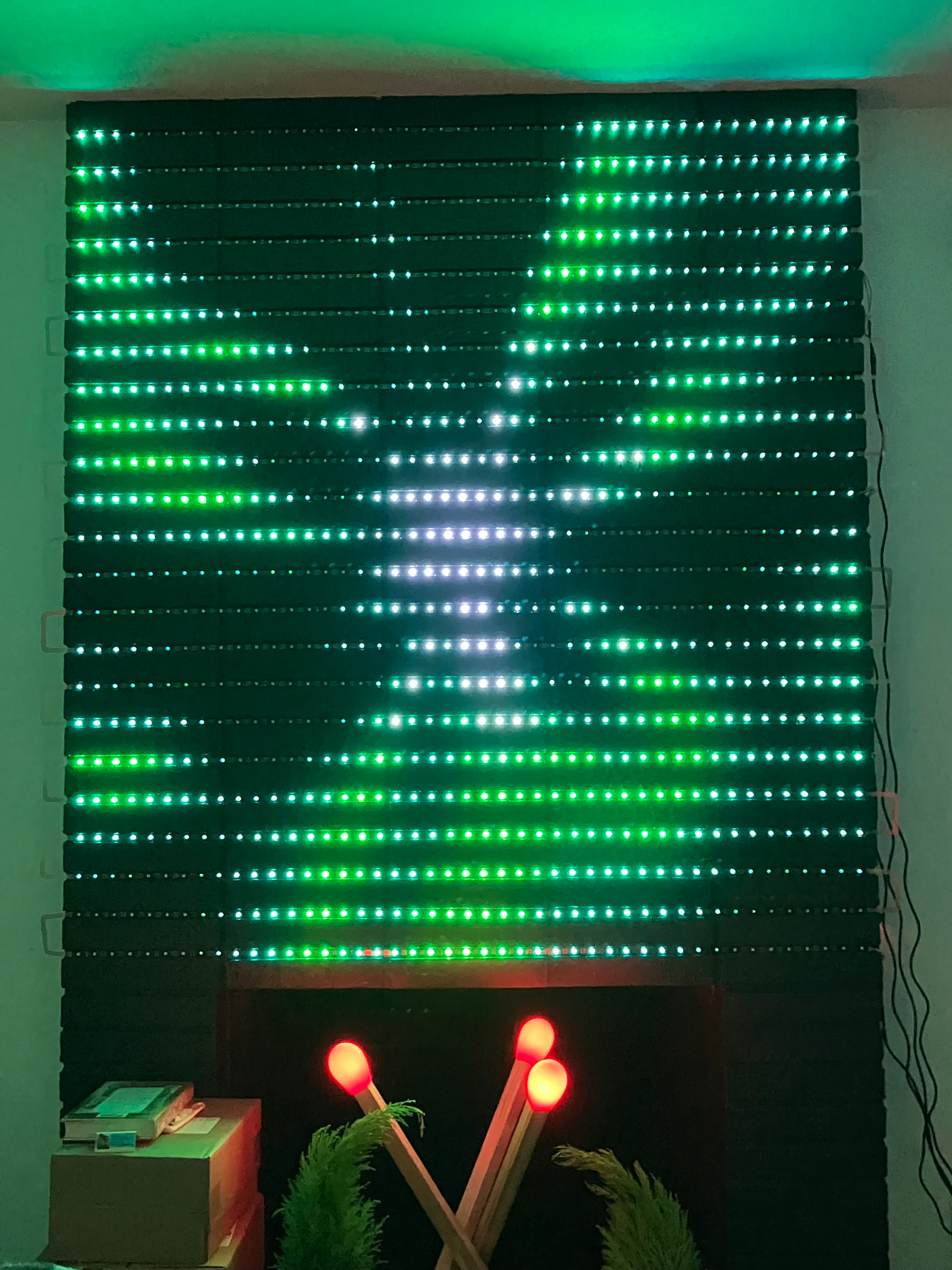
Hi, everyone. I’m super excited to share my fireplace project, it came out even better than I imagined. So I moved earlier this year and the new place has a non-functional fireplace that the previous people painted black because….I have no idea. I think they thought it made this 1960’s bungalow look modern or something. Anyway, it was a big black thing in the middle of a room painted white and it was kind of an eyesore. But yanno what black is great at….being a backdrop for LEDs! And it just so happens that the grout spacing between the bricks was perfect for a typical addressable strip. So I got a pile of HDR SK9822 strips, designed a quick flex pcb with brick spacing to connect them all (because fffff snake wiring 23 strips), hooked up a Pixelblaze, and now have a super bitchin LED matrix in my living room. It’s 45 pixels across by 23 high, 1035 LEDs. I’m injecting power into 4 places, after 270 LEDs. The LED data is currently being entirely driven by one Pixelblaze Standard, but after 10% brightness, it starts to glitch. So I’m going to break it up and put a synced Pico in the middle. The 2D patterns look great, and I soldered up a sensor board so it’s also sound reactive. I also had to get the matchstick IKEA lamp so I could have it in the fireplace under the fire patterns. I’ve also got more build and action videos on my mastodon feed, starting here: Alpenglow Industries (Carrie): "Got an ugly-ass nonfunctional fireplace that some…" - Mastodon 🐘
I’ve still got some buttoning up to do, but this is one of the best things I’ve ever made. It’s really awesome to have a giant LED canvas in my living room, it makes me so happy. Many thanks to @wizard for helping me get the proper mapping and for poking around with adapting patterns. And many thanks to @zranger1 for making some really fantastic 2D patterns.
Already did! One of the photos is the audio spectrum analyzer - it makes singing along to music super fun (my poor neighbors). Making the fire pattern sound-reactive is a good idea, that would be cool, no, I mean, hot!
Thank yoooou! I need to tweak the pad spacing ever so slightly, and then I’ll throw the PCB files up on Github. I think the size of a typical brick is somewhat standard? I’d love to see other builds like this!
Very cool! The form factor is incredible here. There is something really nice about using the existing shape to embed this into.
How deep is the channel between the brick? I’d be super curious about what a diffusion layer would look like over it. I’m starting to like the effect that pixelated diffusion has and this looks like a perfect application.
Thank you! Yeeees, it was so satisfying to take something that was kind of ugly and definitely boring and really transform it. I’ll measure the depth when I’m back home, but it’s roughly the same thickness as the LEDs themselves. They don’t protrude from the bricks. At least in this fireplace, your fireplace may vary!
Yeah, diffusion is something I’m going to look into….sometime. I was talking with Janet Hansen who does amazing LED work in costumes and textiles, and she suggested fabric drapes. I really like this idea because I could choose to have them cover the fireplace, or push them aside if I wanted the pinpoint look. Here are links to Janet’s work if you’re not familiar:
@maumau The depth of my grout varies between about 7-10mm, so the LEDs are definitely recessed from the front of the bricks. I used the backing tape them come with, so I didn’t add any thickness there.
I was thinking about the glitching above 10% brightness. I don’t think that’s a Pixelblaze problem. I recently built a display that wouldn’t go over 40%. Then the LEDs would start to go crazy. The problem was that at higher brightness there was too much voltage drop in the 0 volt return from the LEDs back to where the Pixelblaze was located. This caused a DC offset in the data signal to the LEDs. As soon as that drop gets up to around 1 volt or so (may be 2 volts) during higher brightness transients there can be corruption of the data as seen by the LEDs. Ths comes about because the LEDs’ zero volt reference is then at a higher voltage than the zero volts at the Pixelblaze, and so the LEDs don’t see the high and low voltages in the data stream correctly.
I made a temporary fix by adding a pull-up resistor from +5 volts on the data signal at the PB end (try 470 ohms, 330 ohms, 220 ohms, for example). Note that it’s hard to measure this voltage accurately unless you’re handy with an oscilloscope, since the voltage drop can be rapidly changing depending on the pattern, PWM in the LEDs, etc.
In my case I have a long feed from the power supply and Pixelblaze to where the LEDs are located causing that voltage drop, but in your case it could also just be down to wire size and the number of LEDs (I had only 361 LEDs). I may try relocating the Pixelblaze, but I need a 100% weatherproof housing for it, or I will look at some electronics to shift the voltage more intelligently.
I love the displays, though.
I also have a fireplace to do, but much smaller - I may try something like this.
That’s interesting, thanks for the info. I might try adding the pull-up! I was also thinking of seeing if adding capacitors to the power inputs helps. A little sprinkling of microfarads. I do have the power split into 4, so about 270 per power injection. They’re in a starred formation from the power supply. The Pixelblaze is at the end of the first star leg, just before the LEDs. So there is a fair bit of wire, maybe 9 feet, between the power injection at the LEDs on 4th leg and the Pixelblaze.
Ooooh, please do deck out your fireplace! I’d love to see someone else do this. That reminds me, I need to quick tweak the pin spacing of the flex cable and put it on GitHub. I’ll let you know when I do, assuming you also have standard brick spacing between rows.
Hi - let me know how you get on with the glitching. My panel that had the issue is put away at present until I get a chink of time for some further development later in the year.
As for my fireplace - mine’s quite different - I don’t have bricks to try to line up to - just a space that I’m looking to fill, either with a lighting display, or displaying something else (lot’s of Lego in our house) with some gently animated lighting. The latter option is more likely to be met with approval.
I will! I don’t have a lot of time for personal projects right now, but hope to get back to it in the next couple of months. I’ll definitely update here when I do.
For the glitching above 10%, I’m wondering if the increased current demands start creating a kind of dynamic inductive effect on the signal. I’ve also seen this effect when getting above 500 LEDs on a single channel, especially on a strand form factor where each strand of 50 LEDs was JST connected to the next. I’m wondering about the contact resistance in the Flex PCB design.
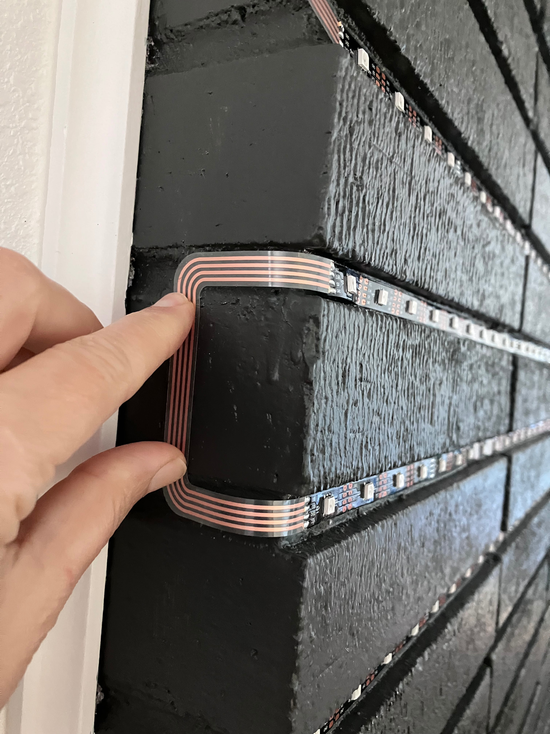
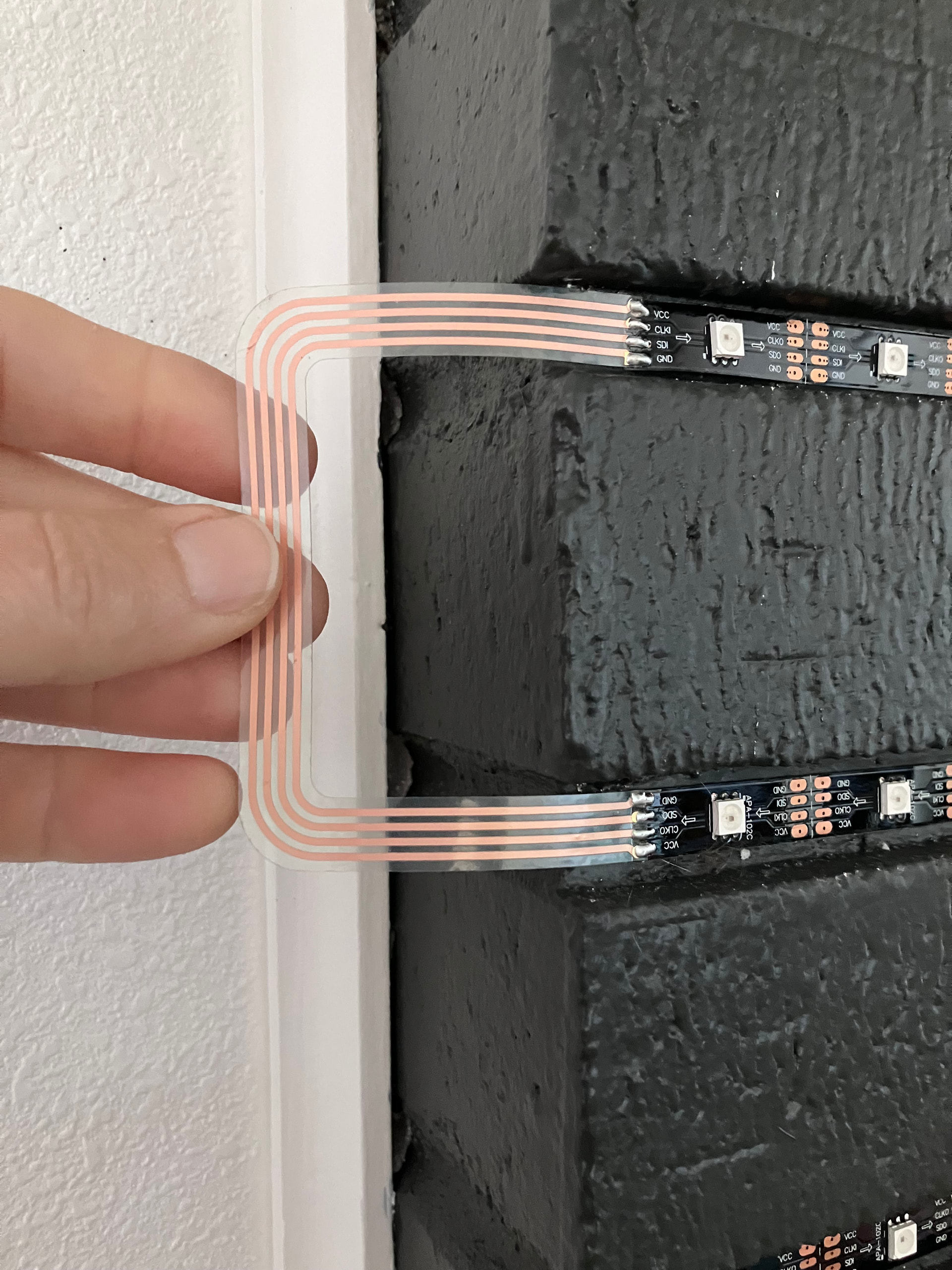
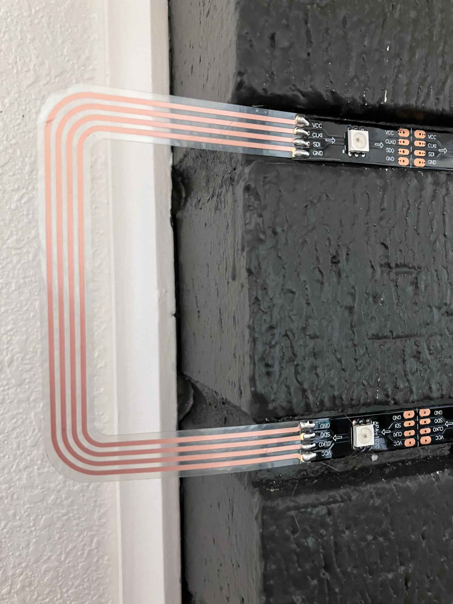
That’s such a cool thing by the way - can you post a closeup shot of those flex PCBs?
Sorry it’s taken me a bit to reply! Yeah, I’m hoping to get back to troubleshooting the glitching in May. Here are pix of the flex PCB, I haven’t attached them to the bricks yet, thinking I’ll use gecko tape to put pieces of clear acrylic over them so they’re a little protected: