Hi all,
I want to add a potentiometer in my pixelblaze v3 board, I have the sensor expansion board so I guess I will be using one of its analog inputs and 3.3v output, is it safe to use the schematic found here:
Thanks!
Hi all,
I want to add a potentiometer in my pixelblaze v3 board, I have the sensor expansion board so I guess I will be using one of its analog inputs and 3.3v output, is it safe to use the schematic found here:
Thanks!
This just came out:
Combo slider and 14 pixels… Sadly no pixel out though (but I’m sure you could open it and add a wire for it)
Hi @Petros ,
Yes, you can use a pot with the sensor board. I would use something like 1K-50K. One end would go to 3.3V, the other to GND, and the tap would go to one of the analog inputs. I would use the 3.3V and GND near those analog inputs as they are filtered and less noisy.
The pot will act like a variable voltage divider, outputting a voltage between 0-3.3V, which will read as 0-1.0 on one of the analogInputs array elements.
@Scruffynerf Yes, add more addressable leds to the project, as if programming for the ones already there wasn’t hard enough already:)
@wizard Thanks! Btw, are there any limitations as to which input to use? I remember reading in another post that some were not giving correct readings due to a bug.
Now I guess I need to get one or more and wire them up, cause I’m imagining adding this as a nice visual slider, with those pixels being useful as indicators like speed or color of the slider…
Sadly like most of the things on m5stack, they are cheap and nifty, but lack something I’d like. The new Pico stamps are cool for just $5… And have a single addressable RGB led built in but lack a DOut there too. I guess they don’t figure anyone would want to hook on more LEDs. ![]()
Any of the analog inputs on the sensor board should work fine.
I’ve connected a 50k pot in A0 and used 3.3v and GND outputs from the sensor board as well, but the readings I get are quite noisy, if I use it for brightness control it oscillates way too much(the 3rd decimal goes all over the place, sometimes the 2nd as well in the vars watch). Is there a hardware way to solve it? I half remember seeing caps connected between the pot terminals in a similar setup once, but then again I’m not sure. I also don’t know how to discard the decimals, what would be the way to do it?
I’ve also connected buttons in the rest of the inputs. In the vars watch I noticed that they are around 0.5 when open(again oscillating a fair bit, but not at all when closed). Shouldn’t they be either 0 or 1, depending on how they are declared in the pattern? The other terminal goes to GND, so once closed they go to 0.
Hi @Petros,
Yes, you can add a small cap from the tap to GND to filter the reading. You might have power supply fluctuations getting to PB, so bulk capacitors could help there.
You can also do a simple filter in code, like a running weighted average (a recursive averager type of infinite impulse response filter, if you want to google digital signal processing terminology).
var average
var weight = .05

function updateAverage(newValue) {
  average = (average*(1-weight)) + newValue * weight
}
Then call updateAverage with the new reading somewhere in beforeRender, and use average for your brightness.
You can play around with weight to make it more responsive and noisy, or slower to respond and stable.
PB is getting power from a pololu step down regulator as I’m powering everything from a 24v source, so there shouldn’t be any fluctuations there.
I will try both cap and code, thanks for the suggestions.
In regards to the button question, in order to get 0-1 when open/closed, should I add a pull down resistor to the analog input and connect the button to 3.3v?
I really cannot figure out how to incorporate the average code. Here’s a very simple pattern, just a solid color. How can I pass the analog input value to the filter?
export var analogInputs

pinMode(analogInputs[4], INPUT_PULLDOWN)

var average
var weight = .05

function updateAverage(newValue) {
  average = (analogInputs[4]*(1-weight)) + newValue * weight
}


export function render(index) {
  h = 1
  s = 1
  v = 1 //analogInputs[4]
  hsv(h, s, v)
}
Oops, I skipped right over the button question. Yes, you would need a pull up (or down) resistor in your circuit for a button.
The analogInputs are not pins on the PB, you can’t use them with pinMode or digitalRead - instead you read directly from those values, and PB updates them behind the scenes. You have to add your own pull up/down resistors.
The values will still be analog, and range somewhere between 0 and 1. To get a true/false value, compare it against a threshold.
So e.g. if analogInputs[4] is your button input and you used a pull down resistor, with the button connected to +3.3V. For example this function would give you a true/false value:
function isButtonPressed() {
  return analogInputs[4] > 0.5
}
Using it to read a button is very different from reading a pot. The averaging code was intended to show you a digital filter for your pot.
Let’s say your pot was connected to analog input 3 on the sensor board. You would have called the function, passing the reading.
Here’s a version with that incorporated, and things moved around a little that hopefully makes it more clear:
var potAverage //read from this in your pattern code instead of directly from analogInputs[3]

function updateAverageForPot() {
  var weight = .05
  potAverage = (potAverage*(1-weight)) + analogInputs[3] * weight
}

export function beforeRender(delta) {
  //other code...

  updateAverageForPot()
}
Step down converters work by switching power on and off (24v in your case) through an inductor, which is then further filtered by a capacitor. The frequency and/or duration that the power is switched on is controlled so that the output voltage across the output capacitor remains close to the target.
With larger loads, there is more demand on that output capacitor, and voltages will dip lower between each cycle.
On top of that, the controller monitoring the output voltage along with the time it takes to adjust power will not be able to hold a perfect output voltage when the current draw changes quickly. The speed of the adjustment is known as its transient response.
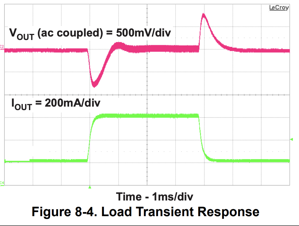
If your converter is this one, from the page it is rated for 4% accuracy on the output. Looking at the pictures it seems to be based on the TI TPS55340. The data sheet for that IC lists transient responses ranging from 500mV to 960mV (varies by design), and has charts like this for their reference designs:
The ESP32 module can jump up to 600mA very briefly when the radio is on, though averages much lower (up to about 175mA). Those changes in current will cause changes in voltage much like the graph shows. That isn’t counting LED patterns causing their own rapid changes in current draw.
It’s not hard to imagine the power fluctuating by hundreds of millivolts, which will make for a very dirty power supply, and add noise to your analog readings (and if they are bad enough, cause WiFi issues).
I recommend adding a bulk capacitor to your power supply, as close to the PB as possible. It will help supply power during those short bursts, and smooth out fluctuations in power supply voltage.
I’m actually using this one, it is rated at 600mA so I need to change it fast, I didn’t know that PB can get to 600mA, I thought it was more than enough! I was just looking at this, it’s rated at 2.5A, more than enough to power PB, but I see it has a voltage dropout of nearly 1v at 600mA, is that normal for such converters? My power source is 24v, so a step down converter will have to be used for PB.
I want to use your debounce code for the buttons, the idea is to increment the hue value by .3 every time the button is pressed. Would it work in the following way? I can’t do any soldering at the moment so I have no button in place, just working on the code.
export var analogInputs
buttonPin = analogInputs[3]
debounceTimer = 0
lastButtonState = HIGH

export function hsvPickerHue(h, s, v) {
  hue1 = h
  saturation1 = s
  value1 = v
}

export function beforeRender(delta) {
  //read the new button state
  var newState = digitalRead(buttonPin)
  //if its the same as the old state, reset the timer
  if (newState == lastButtonState) {
    debounceTimer = 0;
  } else {
    //otherwise add time to the timer
    debounceTimer += delta;
  }
  //if the timer crosses a threshold, then we're sure the state changed
  if (debounceTimer > 50) {
    lastButtonState = newState
    //do something when the new state is low (button pressed)
    if (newState == 0)
      hue1 = hue1 + .3
  }
}

export function render(index) {
  h = hue1
  s = saturation1
  v = value1
  hsv(h, s, v)
}
btw, is 1k enough for the pull down resistor of the button?
Hey there! I can jump in to help with your sensor board code.
Like Wizard said above, you only need to use digitalRead(buttonPin) on GPIO pins on Pixelblaze itself. To grab whether sensor board pin A3 is high or low, just read the value from the analogInputs array directly and assign it 1 or 0.
   //read the new button state
   newState = analogInputs[3] > .5
In addition, you mentioned using a pull down resistor. That means the A3 reading will usually be very close to zero, but you’ll wire your button so that when it’s pressed, it momentarily connects the pin (and ungrounded side of the resistor) to +3.3 V to produce a high value. Therefore, you probably want this code:
//do something when the new state is low (button pressed)
if (newState == 0)
  hue1 = hue1 + .3
to be this:
//do something when the new state is high (button pressed)
if (newState == 1)
  hue1 = hue1 + .3
I tested it, and with those two changes your code works for me!
Anywhere from a 1K or 10K resistor will probably work well. Here’s an article that goes into more depth.
Thanks a lot for the reply, indeed it works!
I’m seeing the following strange behaviour though: If I switch to another pattern and come back to this, last used hue value is not saved, it reverts to the one used when I saved the code. If I remove the part of the button, hue value is retained. Any idea why?
export var analogInputs
export var potAverage

debounceTimer = 0
lastButtonState = HIGH
debounceTimer2 = 0
lastButtonState2 = HIGH

export function hsvPickerHue(h, s, v) {
  hue1 = h
  saturation1 = s
  value1 = v
}

function updateAverageForPot() {
  var weight = 0.01
  potAverage = (potAverage*(1-weight)) + analogInputs[4] * weight
}


export function beforeRender(delta) {

  updateAverageForPot()

  //read the new button state
  newState = analogInputs[3] < .2
  //if its the same as the old state, reset the timer
  if (newState == lastButtonState) {
    debounceTimer = 0;
  } else {
    //otherwise add time to the timer
    debounceTimer += delta;
  }
  //if the timer crosses a threshold, then we're sure the state changed
  if (debounceTimer > 50) {
    lastButtonState = newState
    //do something when the new state is low (button pressed)
    if (newState == 0)
      hue1 = hue1 + .03
  }

    //read the new button state
  newState2 = analogInputs[2] < .2
  //if its the same as the old state, reset the timer
  if (newState2 == lastButtonState2) {
    debounceTimer2 = 0;
  } else {
    //otherwise add time to the timer
    debounceTimer2 += delta;
  }
  //if the timer crosses a threshold, then we're sure the state changed
  if (debounceTimer2 > 50) {
    lastButtonState2 = newState2
    //do something when the new state is low (button pressed)
    if (newState2 == 0)
      hue1 = hue1 + .2
  }
}

export function render(index) {
  h = hue1
  s = saturation1
  v = potAverage
  hsv(h, s, v)
}
Variables with sliders are saved, because slider. Normal variables aren’t saved that way.
And I can’t really think of a great way to store values between power cycles (short of websockets).
I have a suspicion an API to do that might be bad for the flash memory if not used judiciously in a pattern.
Noooo:)
I guess there is no way to pass the value back to the slider or picker after the button is pressed, right?
@wizard , is this something you would consider adding in a future firmware?
Another question, if you notice in the code I’m using a second button to change the hue value more drastically, but I’d prefer to try this with a single button, short press .03 change, long press .3 or so. I understand I have to use a timer for that within the beforerender function, but don’t really understand how, could you give me a pointer?
Now that I think about it a bit more, is to keep the value advancing while the button is pressed, short press .03, long press .03 every n amount of time for as long as the button is kept pressed.
I’m just seeing this post now as I’m wanting to do the same in one of my PBs. This might be a dumb question, but is the code you’ve all posted here needed for every light pattern, or is there some area I’m unaware of to put code that is used across all patterns?
Yes, it is needed for every pattern you want to use the pot.