New to this community and really excited by what I’ve already explored with the PixelBlaze v3. Congrats to the Wizard (or is it Electromage?) for a great product! I have a number of questions I would appreciate your help in answering.
Background
I am looking to get an analog voltage input to drive the LED strip. I found the following example code Automotive use with the Pixelblaze which effectively covers how to read the analog input. I tested it by simply touching the pin 33 with my finger and it responded accordingly. This brings me to my first set of questions:
It appears that analog input can handle up to 3.3V. Is this correct?
So, I have an input that can go up to 4.5V although it is highly unlikely it will ever go above 3.3V. What will happen to the PixelBlaze board (if anything) if the voltage to the analog input (pin 33) exceeds 3.3V and spikes potentially as high as 4.5V?
Do I need to use a resistor in between the analog signal and pin 33 to protect the PixelBlaze board from spiking and if so what should be the resistor strength?
When connecting the analog input, is this as simple as connecting the line to the pin 33 or do I need to have a more complex circuit. Both the device generating analog input and the PixelBlaze will be on the same ground.
Lastly, when connecting PixelBlaze to a 12V LED strip, I am planning on using a small step down DC-DC power converter that lowers 12V to 5V to power the PixelBlaze, while running 12V directly to the LED strip. Should I run the ground from the LED Strip back to PixelBlaze (which then connects to the 12V ground via the power converter) or directly back to the 12V ground line?
Thanks for searching the forums first and finding the voltage divider stuff!
It appears that analog input can handle up to 3.3V. Is this correct?
Yes, for v3 (pin 33), and for the five additional analog inputs that come on a Sensor Expansion Board. v2’s ADC ranges from 0-1V and is on pin 7 of the Pixelblaze header.
So, I have an input that can go up to 4.5V although it is highly unlikely it will ever go above 3.3V. What will happen to the PixelBlaze board (if anything) if the voltage to the analog input (pin 33) exceeds 3.3V and spikes potentially as high as 4.5V?
I checked the spec sheet for the ESP32 processor in Pixelblaze - it says that bad stuff can happen above 3.6V. It’s probably worth setting up a voltage divider to make sure your unlikely 4.5V is divided down to 3.3V.
Do I need to use a resistor in between the analog signal and pin 33 to protect the PixelBlaze board from spiking and if so what should be the resistor strength?
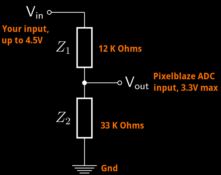
Yes, use two. See the diagram below. You’d be able to compute this by searching for a “voltage divider calculator”, but to reduce a 4.5V max to 3.3V, you match voltage and resistance ratios.
The ratio of the resistor to ground (Z2) vs both resistors (Z1 + Z2) is chosen so that the voltage ratios also match. For a Vin of 4.5V, and a Vout of 3.3V, That 4.5V:3.3V ratio is like 45KΩ:33KΩ. 45KΩ = 33KΩ + 12KΩ.
When connecting the analog input, is this as simple as connecting the line to the pin 33 or do I need to have a more complex circuit. Both the device generating analog input and the PixelBlaze will be on the same ground.
Hopefully the diagram above makes the connections clear!
Lastly, when connecting PixelBlaze to a 12V LED strip, I am planning on using a small step down DC-DC power converter that lowers 12V to 5V to power the PixelBlaze, while running 12V directly to the LED strip. Should I run the ground from the LED Strip back to PixelBlaze (which then connects to the 12V ground via the power converter) or directly back to the 12V ground line?
My guess is you will not need a separate grounding connection between your strip and your Pixelblaze, because it’s most likely your step-down converter will provide this connection for you. If you have a multimeter, check for continuity (0 resistance) between the ground or (-) terminal on the 12V and 5V side of your converter. If they’re connected as mine are, you already have a common ground established. If you want, you could draw out a wiring diagram and take a pic, and we’ll let you know if everything looks good.
Thank you @jeff for such a thorough and thoughtful response. This is indeed very helpful.
To confirm, only pin 33 allows for onboard analog inputs? I thought more were allowed and noticed in the previously linked thread that it appears a software update may have disabled other analog ins. Is this something that may be fixed in a future release?
@ico,
There is a problem with using analog inputs on the other pins currently. I’m looking at possible fixes or work-arounds. I suspect that somewhere along the way a framework update made them unusable. The other pins map to an ADC that is also used for WiFi, and there are comments from the framework developers that they disallow access to avoid possible conflicts with the WiFi drivers. If I can use them in a way that doesn’t cause issues with WiFi, I’ll provide an update that restores analog input on the other pins.
Thank you @wizard. I think having additional analog inputs would be nice for my next project that is designed to scale and therefore the cost is a consideration which may make analog expansion card a suboptimal choice.
It is possible to limit the voltage into the analog pin using a zener diode.
You simply replace the 33K ohm resistor in @wizard ‘s diagram with a 3.3V zener diode (with the cathode connected to the pin, and anode connected to ground). You still need the 12k resistor to limit the current through the zener diode, but the exact value doesn’t matter so much (you could use a 4.7k, or 10k and it will still work just fine).
The advantage of this circuit is that you get full range out of your signal, and anything over range is simply clipped - ie you cant go over 3.3V because the zener diode limits the voltage to 3.3V max.
With the voltage divider circuit, your whole signal is made smaller, so you have less dynamic range.
Jeff, I did check the ground before and after the converter and my Fluke meter shows resistance at 0.3 Ohm. Is it safe to assume this is simply the resistance of the wire itself? Just for good measure I tested resistance using a 6 inches of wire and the Fluke shows similar resistance.