Heya folks – apologies for abusing what I’m sure is already a very well-beaten horse, but I haven’t found quite the right thing in the forums from the searching I’ve done, and I just had what is probably a very dumb and very simple question about pixel mapping.
I need to kind of construct matrix display out of a few LED strips (my test setup has 3 strips of 18 LEDs, for a total of 54), that I’m hoping to set up as an 18x3 ‘display’ (the eventual implementation will be a diffused inner shadowbox frame for a 3d printed topographical map – i’m trying to simulate a sun path).
To set the thing up from a physical layout standpoint, would I set it up effectively as one long strip (the top and bottom strips going one direction, and the middle one reversed)? Should they all be facing the same direction?
With the total number of LEDs set to 54 in the setup tab, would the width be set to 18 in the mapping config, or would it be 3?
I’ve tried several different test patterns just to see if I can’t get the layout down right, but it’s just not super clear to me so far. Thanks for y’all’s patience – cheers!
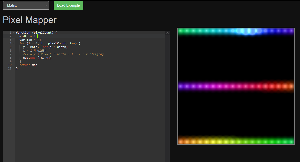
I have the zig zag commented out because my matrix is wired so that each row goes the same direction, but if you had a zig zag setup, you’d want to keep that line in.
If you’re assuming you did something wrong because of the large black space in the preview like you see in my screenshot, that won’t affect things. The coordinates will be normalized to go from 0.0 to 1.0 no matter how many rows you have, so a low number of rows shows a lot of “empty space” in the mapper.
For the physical setup, it’s usually easiest to zig zag, since it has the shortest wire path. Running each strip in the same direction requires running the wires back up to the top of the next strip from the bottom of the previous one.
That all makes sense now. Besides the general unfamiliarity with this hardware and its setup, the ‘matrix’ setup I have here displays a lot of the 2D patterns kinda weirdly (a lot of them seem to not really scale super well to real long, skinny XY setups), so it was a bit hard to tie the observed results of various settings to an expected behavior. Thanks muchly.
To be clear, if you don’t want the “lots of empty space”, which can really break your 2D pattern and make you wonder why it looks crappy, you can use a few tricks.
A - use values to ensure that each axis is consistent. If you have 18 columns, the first and last end up roughly (but not exactly) as 0 and 1, the rest evenly spaced between. While with only 3 rows, they end up as 0, 1 and the one remaining row gets roughly .5
Due to the way PB auto-renormmalizes, you need to either massage the values later (see B) OR trick the normalizer to do what you really want. In this case, 3 rows at the center might be better in many cases, so let’s add some “cheater pixels”… These don’t have to be real pixels, just items the mapper will take into account. So at the end of your mapper, let’s say that the top left is 0,0, the bottom right is 3,18, yes? If we add in a pixel that tell the OB, we really have 18 rows, like adding 18,18, now the 3 rows will all be at the top, and all end up near 0. If you wanted it centered, use two cheater pixels, like 9,18 and -3, 18, and now it’ll be centered (I believe, someone check my math)
B - instead of cheater pixels, use the transformation API that @wizard added, and adjust the scale, so that the row scale matches the scale of the columns. I believe it’s something like 6x so you’d want to multiple the X axis by 1/6 (again check my math, I’m not in front of a PB right now)
Hope that’s clear. I’ll try and follow up when I have a PB in front of me.
That all sounds like absolutely outstanding wisdom, and I thank you for it. I haven’t figured this out enough yet to know what to do with it, but I think this will probably save me a lot of headache in a week or so
Oh that’s on me for sure. I haven’t touched an LED project in probably 3 or 4 years, and just plugged this thing in for the first time ysterday. I’m in the 101 class over here still
Trick C - make the strips into parallel lines at 45°. Then the pixels natually full a square, and the normalization maintains this. … but then you have diagonal lines
Trick D - make a framebuffer and do your own mapping (see the “Yet another approach to text rendering (WIP)” thread for my latest). … but then none of the 2D patterns know about your geometry.
Suppose you have 48 LEDs and you want to place them at integer coordinates. One line is (0,2)-(15,17) another is (2,0)-(17,15) and in between you have (1,1)-(16,16). Then the map fills an 18x18 square and after pixelmapper normalization, just rotate it by 𝜋/2 and scale it by 1/√2 and you have 3 parallel grid-aligned lines of length 1!
There’s no problem that can’t be made more fun by excessive application of trigonometry!
AH. I see what you meant. 3 lines diagonally instead of horizontally. (My brain was trying to cross the lines to make a square…) And yes, rotation without some scaling down will make the ends exceed the 0…1 range, in that case, so you’d need to do both, but yes, that would be a good method. Lots of ways to do this.