Aurora on LED strips

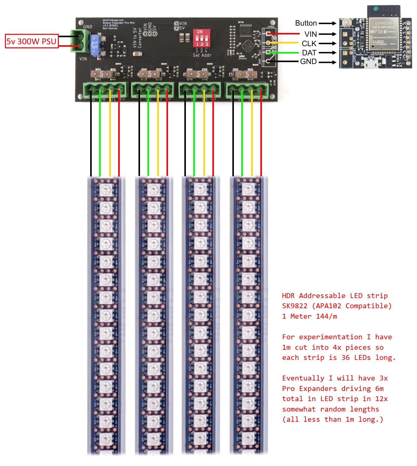
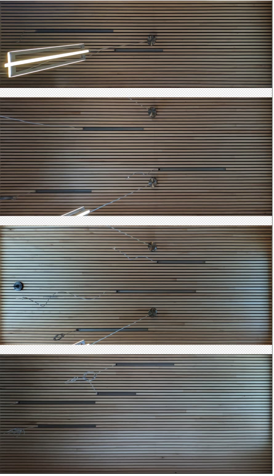
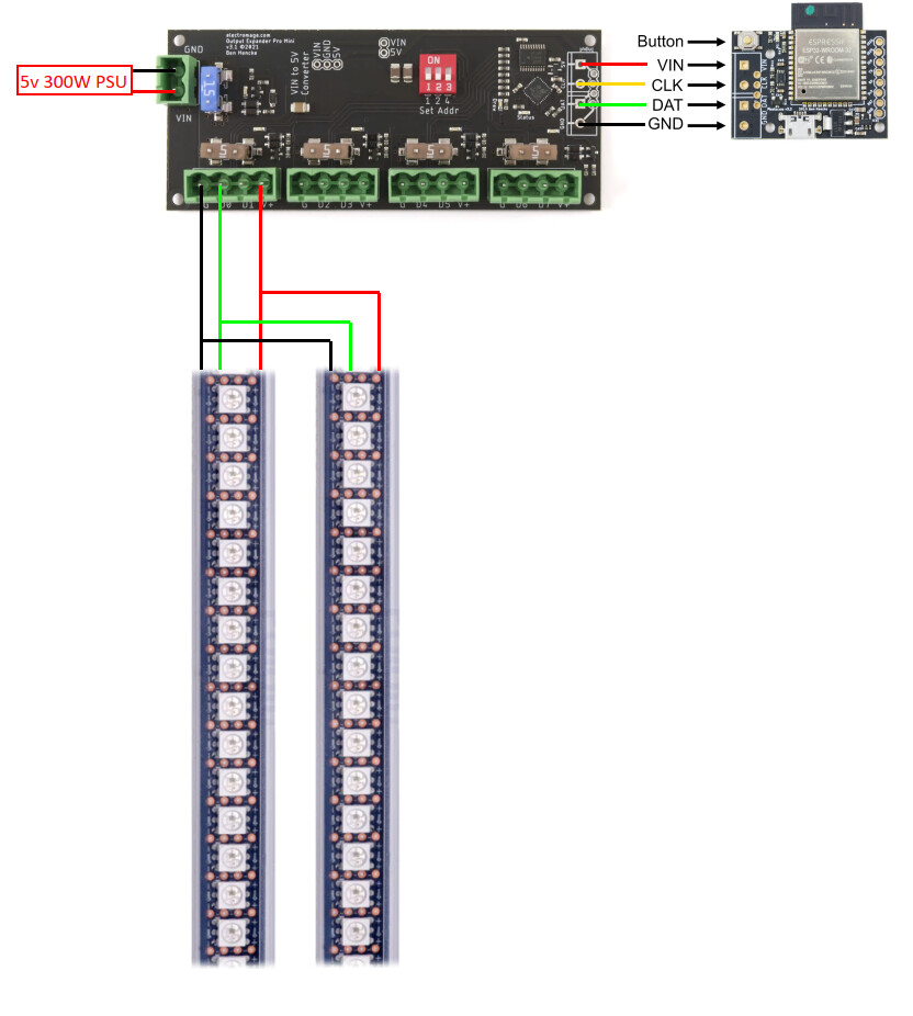
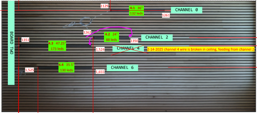
I’m planning a project that involves ceiling mounted 12x LED strips of varying lengths, longest no more than 1m, a total of 6m. I’m thinking of using the 5V 144LED/m strip (would take about 7x strips counting some waste) and powered by 3x of the expansion board pro which should be enough power for all this.

(1 Meter 144/m = 7.6 A. Approx 2m on each expansion board.)

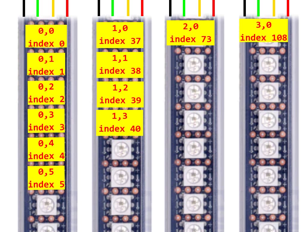
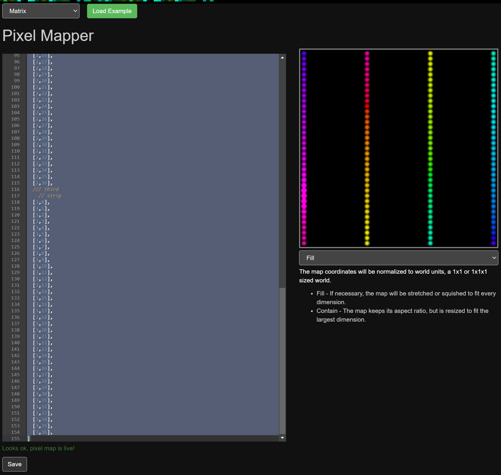
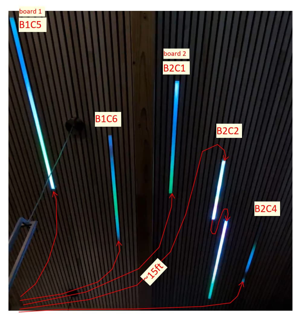
The idea is to display patterns, particularly the northern lights, using this “array”. It isn’t exactly a matrix or grid because not all strips are physically aligned, or the same length. But it could perhaps be treated as a matrix…

Any comments on my hardware plan?

Also any hints as to get started coding this? I’ve written a little code in the past but it has been a while and this is my first time with the PixelBlaze.

Ideally I’d be able to create a multi button control panel where each button starts a different pattern playing back - as well as being able to control via wifi…

thanks!

144LED/m x 6m = 864 LEDs which can easily be driven by a single Pixelblaze. You’d just have to inject power at various points, but that should be simple since it’s a planar layout.

The pixel mapper lets you assign a location to each LEDs, so you’re covered as far as layout goes.

Then you could use the built-in Perlin noise functions to make the aurora. Coding would be relatively easy.

Wifi control is done via the built-in web interface. As for buttons, you could start by wiring to the built-in button which advances to the next pattern in the playlist. For multiple buttons direct to specific patterns, right now I think you would have to bake all of your patterns into one, then switch behaviour based on a button press. Actually I would suggest potentiometers driving a single pattern … attach a physical slider to color/speed/noise parameters and then you have basically infinite combinations. You can do a bunch of that via the pads on the back of the Pixelblaze, or add a sensor board for easier connections and audio feedback!

Thanks! I’ll head that direction, will probably be back here in future :slight_smile:

Hardware plan sounds solid.

For mapping and programming, it all depends on what you want it to look like. You could map it out even if things aren’t perfectly aligned, it would just mean a bit more mapping work.

If you can draw up a sketch of what you have we can give more specific advice/help on mapping.

There’s an intro to Pixelblaze code pattern, I would definitely run through that as it covers the basics! From there you could use some of the existing patterns as a starter, or make your own from the basics like time(), wave(), maybe some perlin(), and so on.

For the button control stuff, check out the relatively new sequencer API. That would let you write a bit of code (copy to each pattern) that checks for buttons and jumps to a specific playlist item.

Great, thanks. I ordered some materials to start messing around with.

The PixelBlaze has arrived and I’ve soldered it up and applied power and cut up the 1m of 144/m SK9822 into 4x pieces and am successfully sending patterns to the LEDs.

Because the strip isn’t meant to be cut that often I’ve “lost” the last LED on some strips, which raises the question: does it matter if I tell the PixelBlaze there are 36 LEDs on a channel when only 35 are working?

Here’s the hardware diagram:

Right now all 4x strips are acting in unison.

I’ve run through the coding examples, understanding some of what I read…! I get the general principles and can make the LEDs change color etc.

However I’m not sure I understand the mapper properly. For one thing, pasting in examples in the mapper dialog doesn’t seem to actually affect what is “playing” on the LEDs - the pattern I previously selected on the Pattern tab is still playing, even though the Mapper page says “Looks ok, pixel map is live!”

As I understand it I need to enter a map of my physical LEDs:


(only some labelled to save time!)

So then in the JSON format this would be:

[
[0,0],
[0,1],
[0,2],
[0,3],
// and so on to 36 count
[1,0],
[1,1],
// and so on to 36 count)
// repeat 2x more times for the 4 total strips I have (12 times in the final incarnation)
]

Does this look right? I did this and clicked “Save”, page says “Looks ok, pixel map is live!” and a preview is playing on the right, but nothing has changed on the actual LEDs - they are still outputting the last pattern I chose… And all 4x strips are doing exactly the same thing still.

What am I missing here?

thanks!
Jon

Not really, you just lose the pixel. If it makes things easier for you, go ahead.

Yes, though I think your second strip would start at index 36 (since it starts with zero). Your map wouldn’t change.

That totally depends on the pattern, and what the pattern is doing with the map information. Your map looks correct though!

Each strip is going to have a different X coordinate, so try a pattern that does something different based on that. Some patterns are 1D only and would need a render2D added, but many are 2D/3D capable which should do something different with the X coordinate.

Try a simple pattern like this:

export function beforeRender(delta) {
  t1 = time(.1)
}

export function render2D(index, x, y) {
  h = x/2 + t1
  s = 1
  v = 1
  hsv(h, s, v)
}

That should show different colors on each strip. The y coordinate isn’t used, so each would be a solid color, but all 4 should show a changing rainbow.

Older versions of Pixelblaze would let you overlap address space with the output expander config, so send us a screen shot of your config and/or update to the latest version and make sure you have a unique contiguous address space. That is, make sure each strip have different start indexes, and are 36 pixels long. The auto button can help once you put in counts.

That was the problem.

1 Like

I’ve now started the real project. I ended up moving to 12V pro expanders because 5V would have too much voltage drop.

Here’s an approximate ceiling layout based on some stitched photos:

I then assigned # of LEDs to each strip, and used a PDF dimension tool to tell me how many “pixels” everything was apart, then made a spreadsheet with “addresses” of the LED strips in the correct rows/columns, and then used the super helpful LED Mapper to make the JSON map. Somewhat surprisingly it seems to have worked pretty much on the first try:

Now I need to finalize the wiring and mount the LED strips in their slots and power everything up…

However I could use a little help in the pattern programming. I understand enough of the patterns to alter speed / colors and so on, but don’t understand @sorceror 's suggestion to use “built-in Perlin noise functions to make the aurora”.

The closest I’ve got so far is to edit the “green ripples” pattern to run slower… It is ok but not great. Ideally one would have some reds in the Aurora anyway.

Any tips would be appreciated!

thanks - Jon

1 Like

Hi @jonb42 ,
Awesome!
Here’s the release notes when perlin noise was added:

There’s a few examples in there. You can find the API docs below the editor, built in to Pixelblaze.

You can also poke around with these patterns to get an idea of how people have been using them:

1 Like

I haven’t got to the perlin implementation yet, have another hardware question first:

If I run two LED strips in parallel, both fed from the same channel data wire (these are WS2815 strips) will they show exactly the same pattern? Or will there be an address conflict?

1 Like

Yep, tie the data inputs together and both will get the same data, and act as mirror copies of each other.

It can have issues if the data wires are very long, but usually works just fine.

When wired like this PB only “sees” one copy of the strip.

1 Like

I am driving two strips in parallel and they are stuck back-to-back, then one of them has all 4 wires going (data) downstream. Should I connect the power+gnd where the strips end? Power might be coming (data) upstream, in case that’s relevant.