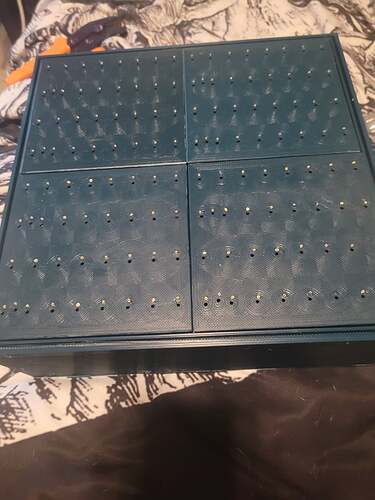
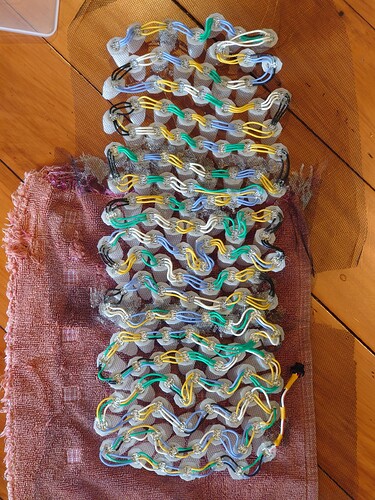
So I’m back. I’ll try not to let this thread turn in to another sprawling monster like the last one lol. So here’s the deal I’m about at the point of assembling the LED planes in to the PCB (in photo below) and I’m not quite sure how I should connect the data points. The construction of this is based off of the design MaltWhiskey did for his 16x16x16 cube. I’ll link the video down below for reference.
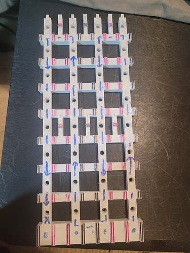
What I’m going for is ease of programming for patterns, mainly because I’m clueless at it so I’m gonna be learning on the fly. There’s going to be 4 separate PCBs with 8 LED planes on them each (photos below).
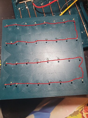
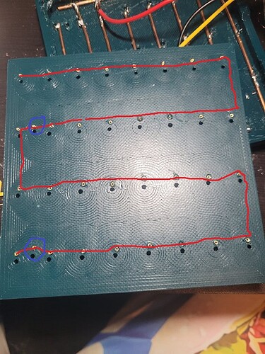
As far as the photos, blue circles are my potential data points going back to the Pixelblaze and the red lines are potential data paths. Would it be easier to just wire each plane on the PCB in to series so there’s only 4 channels going to the expansion board or is that going to limit me on patterns or make coding worse. Or should I have 2 separate channels per PCB, one channel controlling half of the PCB (this is how MaltWhiskey did his). Or does it really matter? Is it just something I’d have to potentially adjust in the code? Kinda stumped as this wasn’t really explained well and I’m just unsure how to proceed.
I have the feeling it doesn’t really matter and it’s gonna just be up to coding but I figure I’d ask for advice.
