Just wanted to check if doing so will show the jack as permanently connected, which would disable the mic. Not likely, but I figured I’d ask.
Yes it can be, and would disconnect the mic. Some of the remaining holes could then be connected to reconnect the mic.
Good to know, thank you!
Ok, I’m trying to figure out what to connect where in order to desolder the audio jack and keep the mic functional.

No pin numbers on the schematic, so maybe it’s easier to see on the layout:
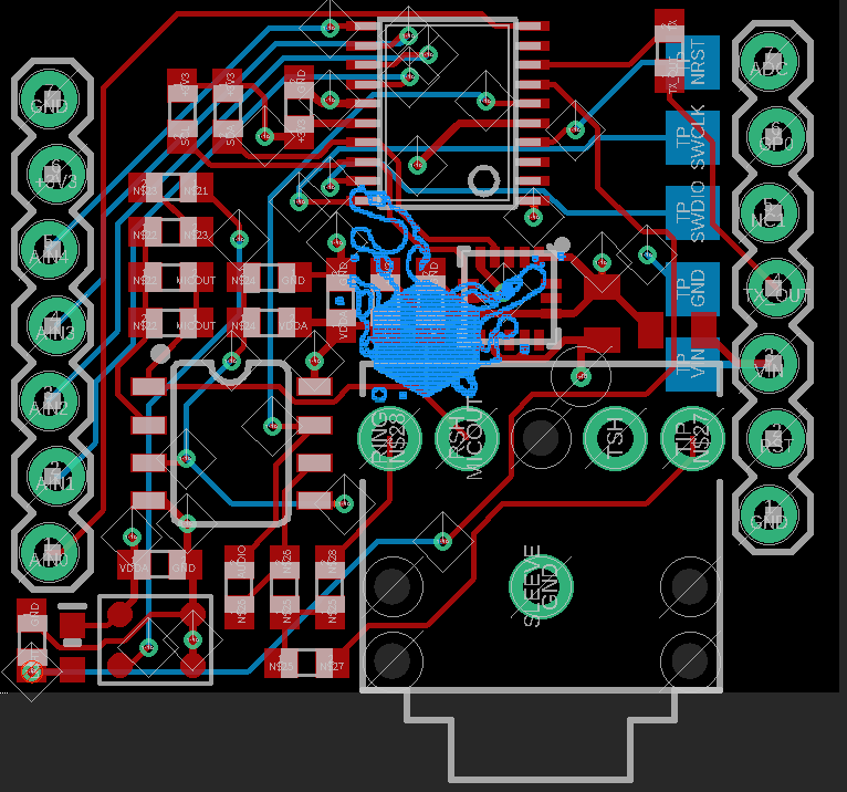
Could you please tell me which of the 4 jack holes should be connected to what? (ground, presumably?)
Thanks!
Should be the 2 under the blue cube. If you test the jack pins, these should be shorted when no cable is plugged in and open otherwise.
You can see one is mic out, that goes to n$28.
Ok, so just to make sure I understand. Let’s number them 1 (RING N$28), 2 (RSH MICOUT), 3 (TSH) and 4 (TIP N$27).
On an intact sensor board:
Nothing plugged in:
1-2 shorted.
3-4 shorted.
1-2 not connected to 3-4.
1, 2, 3, 4 not connected to ground.
Jack plugged in:
1-2 open
3-4 open
2-3 open
1-4 connected but continuity test takes a little time to register.
1 and 4 connected to ground through 16 Ohm.
So, for a board with the audio jack removed, I should short 1 and 2 so that the sensor board enables the mic?
EDIT:
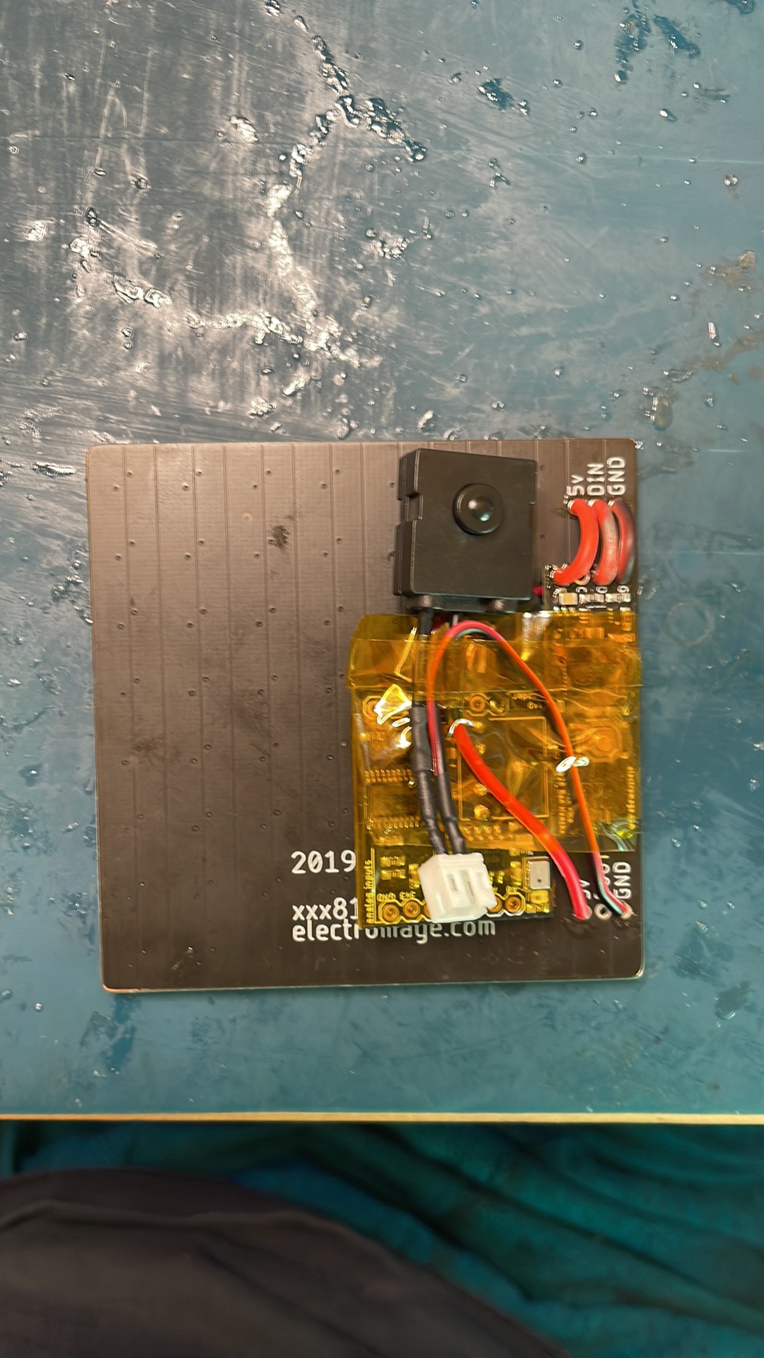
Happy to report that the Sensor Board and Pico can survive 3v3 being wired to the SB’s TX. ![]() , also shorting 1-2 works perfectly.
, also shorting 1-2 works perfectly.
1 Like