Good day all,
This request for a nudge on the right coding direction is specific to my 5 Compound Tetrahedron model.
I’m attempting to learn pattern generation on the PB and I think I have a basic grasp and can figure out how to tweak existing patterns to desired effect. I have also produced a 3D map (in cartesian coordinates) and it looks good with pre-built patterns.
The way the model is built each ‘spike’ of a tetrahedron has 4 individual pixels in that are aligned so that one is aimed at each face of the mini tetrahedron and one aimed directly at the vertex. These 4 LEDs/Pixels are not shielded from each other so colour can blend on the white PLA surface to good effect. As a group these 4 pixels are shielded from the adjacent ‘mini tetrahedrons’ so clear delineation is possible between these areas. Hopefully I have explained the arrangement well enough for people to understand.
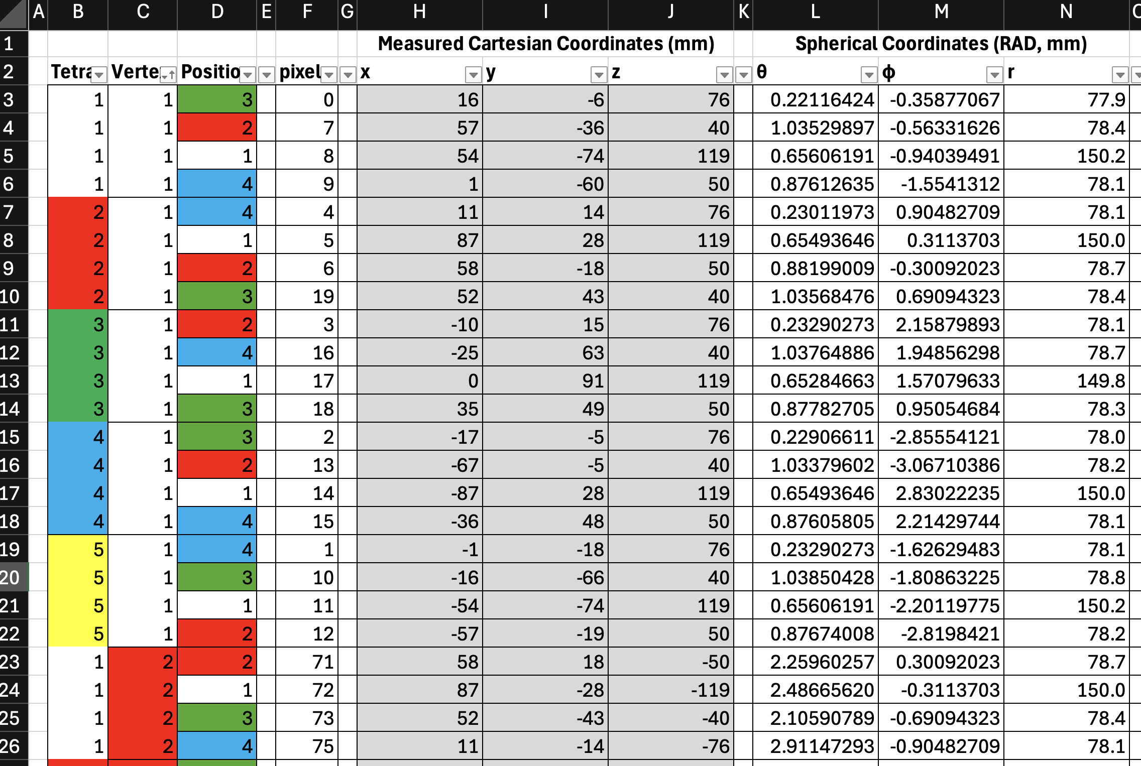
I created a topography for my own sanity by dividing the piece into tetrahedrons (1-5) then each of those is subdivided into Vertex number (1-4) (the mini-tetrahedrons) and then within a vertex/mini-tetrahedron each individual pixel (1-4). So for example 2.1.3 is the 3rd pixel in the number 1 vertex/mini-tetrahedron that is part of main tetrahedron 2. Each allocation also has a colour in my system.
A picture paints a thousand words and all, so here is a screenshot of my excel sheet for the mapping (including the naming system above, the cartesian coordinates measured manually and calculated spherical coordinates in case I need them later).
And the corresponding model in sketch-up looks like:-
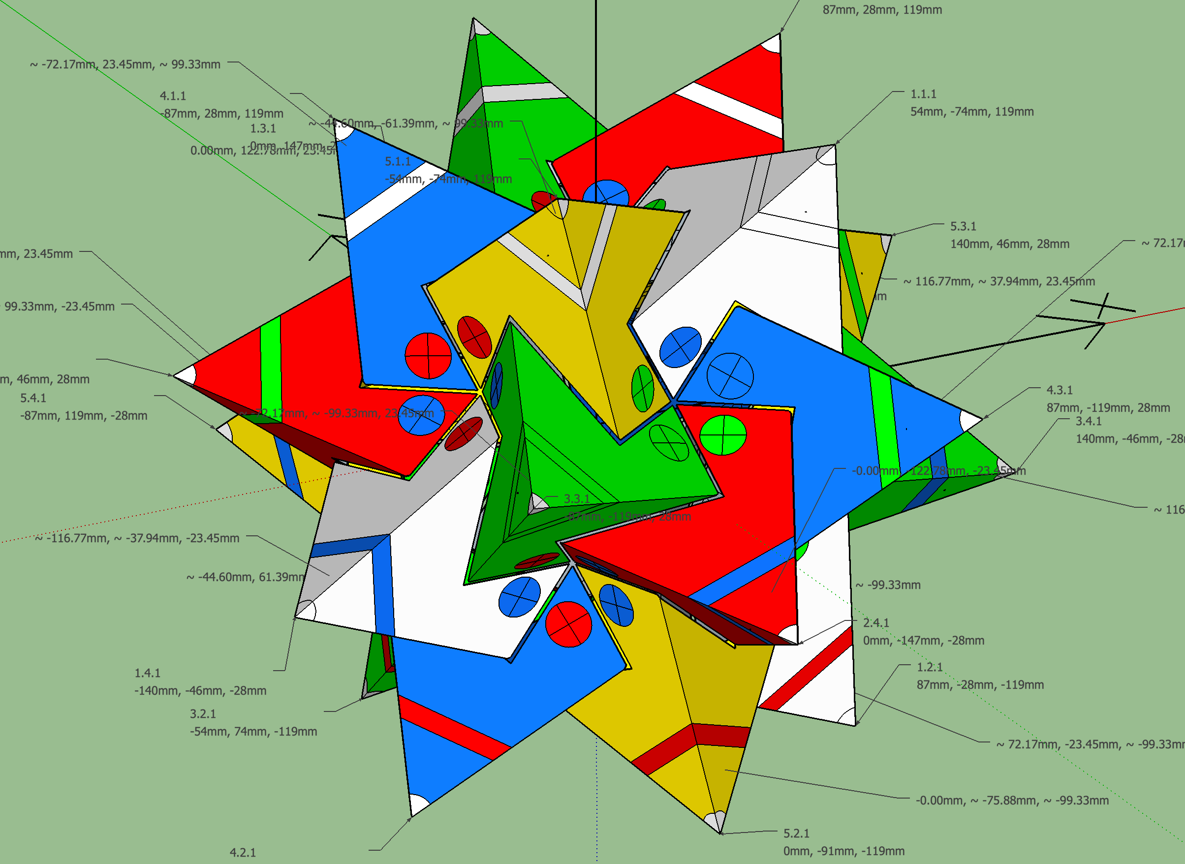
My aim for using this system of addressing is so that in order to light all the parts of one entire tetrahedron I can just set the colour for all Pixels at the ‘address’ of that tetrahedron using a mask i.e. 1.x.x will be all LEDs of Tetrahedron one (the white on in the image above) and 2.x.x will be all of Tetrahedron 2 (Red) for example. If I want to set the tip of each vertex to a certain colour then I can just mask for x.x.1 (as the address assigned to each led within its subgroup is always the same). There is also a logic to how they are assigned i.e. the 3 base LEDs within each sub-tetrahedron sequentially rotate clockwise when viewed along the normal of the tetrahedron spike.
Link to sketch-up models of addressing and excel sheet here (side note: I tweaked the coordinated for the 3D map by bringing the distance from the origin for the 20 led that are aimed at the very tips because it made the 3D patterns look better.)
What I really want to do is use this mapping/addressing system to make patterns easy but my maths and soldering are WAAAAAAY better than my coding ability.
So my initial question, is how can I best store and manipulate my address system in code? (I’m assuming there is no other way to do it other than copy and pasting into the bottom of each pattern code some kind of array) But I just can’t get there with my coding ability so would appreciate a nudge.
Sincere thank you for reading this far if you have, this project has lived in my head for years and I’ve returned to it several times. Hopefully going ‘public’ with it will finally encourage me to finish it. I’ve been reluctant to post as I am in awe of the software ability of many people here, but I’ve built up to it and any suggestions, pointers etc would be hugely welcome.
Regards - Woody