Hey friends. What is the correct/safe way to hook a 12V battery to a Pixelblaze Pro Expander (12V)? I keep getting over-current problems when I connect one.
12V battery wired into the input on the board (red to VIN and black to GND). Expander has the built-in 12V->5V DC converter. Pixelblaze controller is soldered on the other end with correct wiring. GS8208 LEDs are wired into the LED outputs (red/V+, yellow to first data connection (e.g. D0/D2/etc), and black & green to G).
The system is powered on when I connect two Anderson type connectors together between the battery and the board.
What happens is it works fine for a little while and then eventually destroys the board. I can smell that something got overloaded (ozone/burn smell). Fuses don’t get blown. Thought I had a bad board the first time but it’s happened twice now. The battery is a brand new Li Time LiFePO battery.
Do I need some inline switch with a fuse or protector of some kind? I feel really dumb and frustrated but I’m not sure what I’m doing wrong. Thanks for any advice.
Hmm. That’s weird. Did you happen to have a multimeter to verify the polarity? I mean, that sounds unlikely with red always being positive on LiPos. And just to verify, you’re using a 3S, correct?
Which board is getting blown, the pro expander or the Pixelblaze?
Hi Jeff. The polarity should be right. I’ve read the battery and board with a multimeter and voltages are normal (13V and change for a mostly full battery). If by 3S you mean the V3 Standard Pixelblaze then yes, that’s the one.
It is the Pro Expander that fries. The Pixelblaze seems fine. I was able to connect it to USB and operate it after losing the PE board.
Is it possible to over-draw power if too many lights are on one output? Trying to think of anything that could contribute.
Ok, yeah 13V is normal for a 3S lipo battery. 3S means 3 cells, 3.7V per cell is nominal and they charge up to 4.1-4.2V, so a normal range is 14.6 V full, discharging to about 9.3. That’s the right kind of LiPo.
I would think that over-drawing the lights would blow an onboard fuse before it blew a component on the pro expander.
With nothing plugged in, and the Pixelblaze disconnected from the pro expander, can you use your multimeter to check the resistance across your Pixelblaze’s 5V and GND pins on its output pins? I’m wondering if you have a short somehow on the PB’s regulated Vin side (which could be the case and you could still power it off USB successfully, since that’s after the regulator).
Thanks Jeff. I’m not sure if it’s 3S, I can’t seem to find it in the specs.
With the multimeter I get ~13.3V on the input terminals as well as the LED output terminals. I can read 13.3V on the IN+ and GND on the DC-DC converter if I position it right. I don’t get any reading on the 5V side or on the V+/GND on the 5V Pixelblaze terminals. I don’t seem to get any readings with the Ohm/resistance setting on the converter.
Ok, that all matches what I’d suspect for a blown 5 V side of the dc dc converter. What would be interesting is to know the resistance reading on the Pixelblaze itself (disconnected from the pro expander as I described above) so we can see if there’s a short.
These results were kind of odd. I don’t read any resistance on the 5V/GND pins that are directly connected to the Pixelblaze (whether USB is power on or off). The first time I measured it, I powered from USB and the conductivity tester on the multimeter beeped but reads 0 ohm. The second time I tried it it doesn’t even beep
I don’t think a resistance measurement across gnd and +V means much when it’s powered by usb.
If you see a value at 0 or near zero across those two pins when everything is disconnected and powered off, that would exactly explain why your pro expander keeps blowing.
The only difference is that the pre-soldered variant comes a JST-XM connector soldered on the PB’s output side so you can use the premade wire harness adapters; for some people that can result in no need for any soldering, but with the pro expander, you’re definitely doing some soldering anyway. Just for an abundance of clarity, the pre-soldered version wouldn’t affect my recommendations here. We’re chasing down a theory that somewhere along the way your PB’s pre-regulation side got blown or shorted, which would explain why the 12V → 5V buck converter on the pro expander keeps blowing up.
Could you first verify the multimeter measurement I’m trying to understand? It’s the one where everything is disconnected (no USB power, no Pro Expander), and you measure the resistance across V+ and GND on the output side of the PB.
You said,
But I couldn’t tell if you measured the resistance with no USB power connected and the Pro Expander disconnected.
When you say that you “don’t read any resistance”, it’d be helpful to clarify if you see a “high” or “no reading”, or if you see 0 ohms. Those are two very different states.
Also, most multimeter’s I’ve used only beep if they’re in the continuity detection mode; some might combine this with the resistance measurement function I suppose, and beep if the reading is below some threshold. So worth checking you’re in the right mode.
If it reads less than an ohm, I think it might be helpful for some pics of the Pixelblaze, and @wizard should give an opinion. If it was a manufacturing error, I think he’ll want to take care of you with some replacements.
Ah I see, sorry for the confusion. I measured resistance across V+ and GND on the unplugged Pixelblaze, not connected to the Pro Expander, and it has no reading (open loop).
Hi @larana ,
The replacement cooked too? I had mentioned this in the email when I sent the replacement:
So with batteries, they can put out a lot of inrush current when connected. That might be causing a transient spike, but I wouldn’t expect that without a large capacitive load attached.
Since it wasn’t a one-off bad board, this seems to support this theory. Aside from the expander board, is there anything else connected to the circuit when you plug in the connector? How much wire do you have from the battery to anything that draws power? Any branches/splits? Wire thickness?
My guess is that you’ll need something to limit inrush current, and/or a transient voltage suppressor. I’m hesitant to throw out solutions without knowing more about your system.
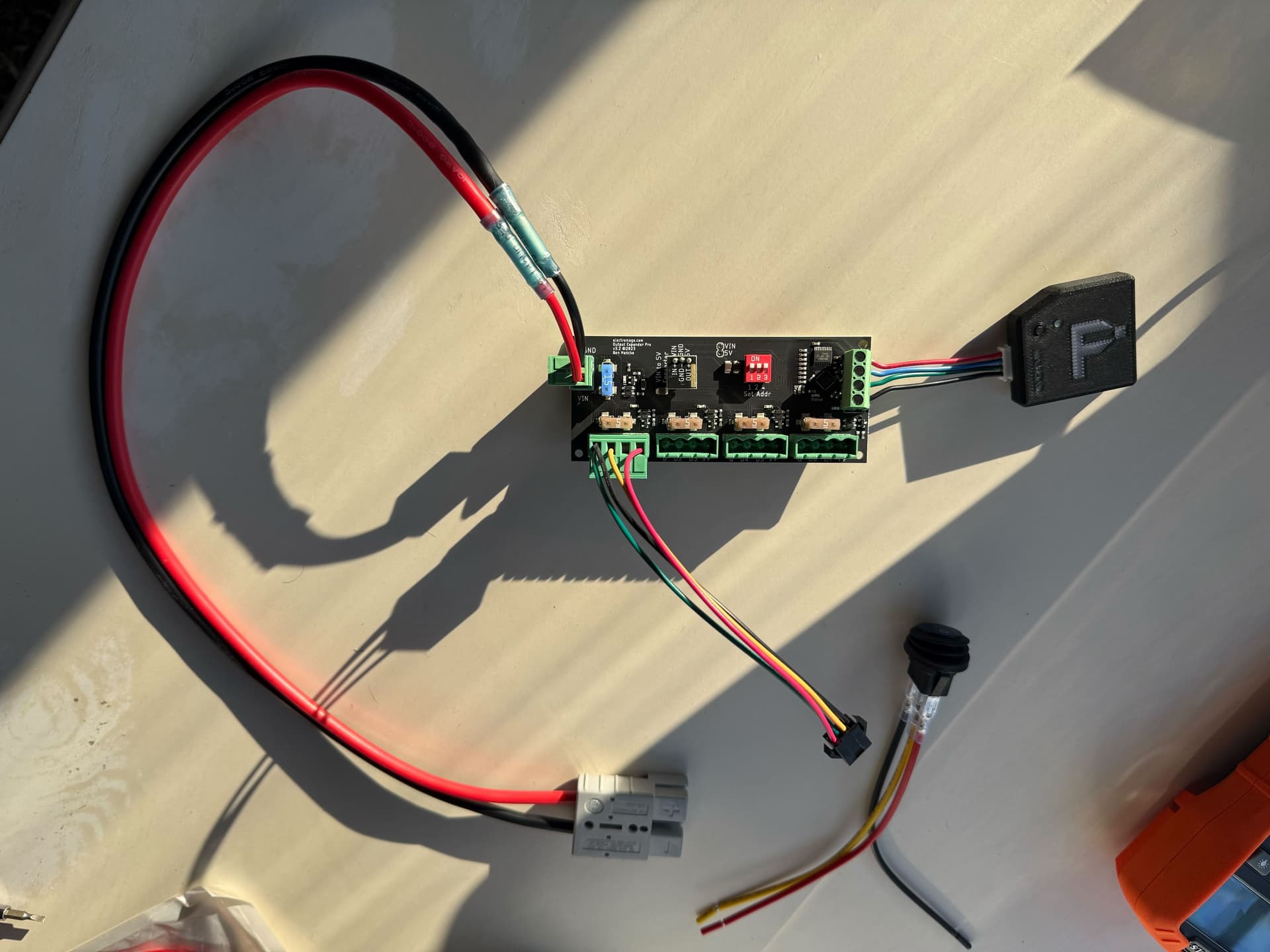
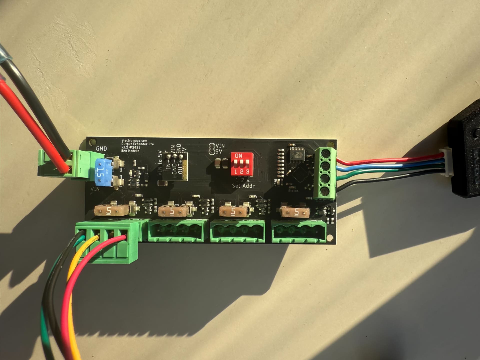
Here are two pictures of the setup. Easier to look at than describe. If you spot any errors let me know. This is new hardware that I won’t connect to power until we have an idea what’s going on.
The gray connector is a quick-connect that is commonly used in battery applications. I also pictured a little switch I bought that I eventually plan to put inline. The battery cable has a 10AWG but that’s too large for these connectors so I stepped it down to a smaller gauge (I think 14AWG) with the splices you see.
These go out to GS8208 lights. Thanks for any guidance!
How much wire do you have between the connector and the battery?
I can’t see anything wrong per se, but I wouldn’t hook it up until we know whats causing things to cook, since it would likely cook this one too.
Can you put the blown expanders in the mail using the return label I sent with the replacement? And if you had a dead PB, that too. If you have time to wait, I’d like to diagnose them before recommending next steps. I’ll replace or refund any beyond the replacement already sent. I don’t want you to feel like you have to keep buying them just to have them smoke, but give me a chance to collect info and make a recommendation before you connect this next one
Sounds good, I really appreciate the help. I don’t remember seeing the return label when I opened the replacement but it’s possible I missed it and threw it out. I can pack it up and ship back though, no problem.
The original PB ‘seems’ ok but it could be damaged somehow as well so I will send it along too.
Oh and there’s about a foot of cable from the battery to the connector and close to 2 feet on the input side (pictured).
I just wanted to follow up here for anyone who may find themselves in a similar situation of connecting a large LiFePo battery bank to Pixelblaze. After some discussions and troubleshooting with support, it seems indeed that the inrush current of the large battery causes a spike that can fry the electronics (seems the 5V buck converter on the Pro board gets cooked first). I played around with a setup that uses an inrush current limiter with 1 ohm resistance and that worked, but the little component gets incredibly hot. Since my setup will have the electronics in a sealed box, the heat output is problematic for me. I started down the path of wiring up a relay timer that would bypass the ICL after certain number of seconds but it started to feel overly-complicated for such a simple thing.
I finally ended up finding this component that can take variable voltage input and send a clean 13.8V output signal with internal over-current protection. This has worked well so far. It gets warm slowly, and eventually gets hot, but not nearly as hot as the ICL did. Since it is IP68 waterproof rated and has mounting holes, I can mount it outside of the box safely. It can also handle 20A (lots of these types of components have lower limits like 5/10A). Hope this helps someone else down the road!