I wouldn’t be using the USB connector on the Pixelblaze itself, just a separate breakout board wired to the buck connector for 5v/ground, and wired to the Pixelblaze for data.
I have read a bit of info about USB only being rated up to around 1.5-2A, though thinking about it, is that due to the individual wire size? As I just had a thought that I could perhaps split the 5v at the first breakout board, and essentially use 2 of the wires in the USB cable to carry the power, then just have 2 separately powered LED sections(1 ring & 1 strip per wire) which if it would work out, would basically be able to supply 960mA per section of LEDs; or is the actual 5v wire in a USB cable a different size, and specific for carrying that 5v?
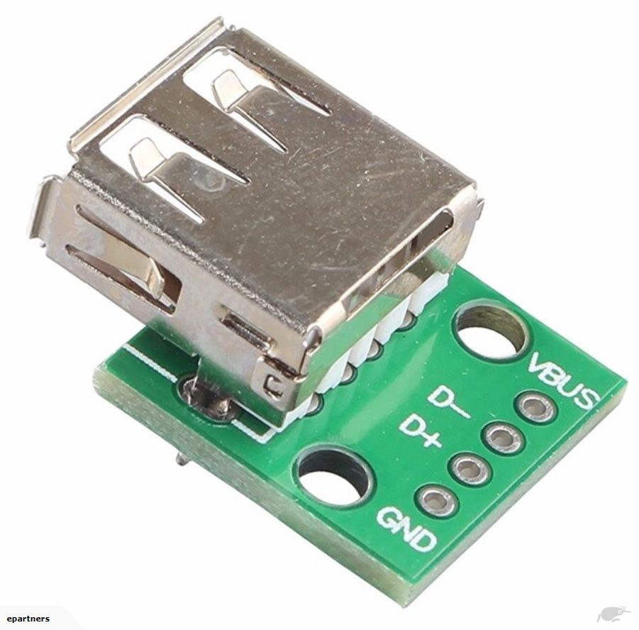
So this is the Type A breakout board I planned on using on the Pixelblaze, buck converter side, so was thinking if I wire the positive to the VBUS & the D- terminal(then data to D+ & ground to GND) and continue the split on the cluster side for the 2 sections of LEDs. Would this work? Or is it the entirety of the USB cable only rated up to that 1.8A?
A quick read of that Wire Size link you post, and some more research points towards the individual wires in a USB cable being around 24-28AWG each, which even a data wire, that could be as small as 28AWG can carry 1.4A, so splitting it, in theory, would be safe to supply my approximated draw of 960mA.
Please forgive my ignorance in all of this, I don’t have the most knowledge when it comes to these sorts of things; it’s mostly just research & tinkering in my spare time haha.