Consecutive LED Strips not Lighting Right

Got 4 tracks of 12V WS2815 strips installed in a room in the basement connected to a PB v3 in the utility room 10 ft away. 239 pixels per track for a total of 956. (see photos). Let’s call all ends on the left A1, B1, C1, and D1 and on the right A2, B2, C2, and D2. All strips are powered individually at points A1, B1, C1, and D1. The data line zig zags and hits A1 first then connects A2 to B2 then B1 to C1 then C2 to D2. Track A works beautifully. All pixels at full brightness and respond to all patterns perfectly. Track B lights up fully but with random static pastel colors, Track C lights up with random, but more saturated colors about 1/3 of the way, and the rest of track C and all of track D are dark.
It almost behaves as though it’s suffering from voltage drop, but each line is connected back individually to the 12V 40A power supply. Is it a data problem? Anyone have any ideas?

Wish I could post a couple more pics, but it looks like I’m only allowed one…

1 Like

Here’s how it looks on full white

1 Like

Hi Andy,

Welcome to the forums!

Since your power supply seems sized appropriately, this strikes me as likely to be a data propagation problem, especially because of the very long serial run you’re attempting. Many controllers support no more than 510 or 170 pixels per output to keep frame rates high and avoid these problems.

I’m going to list some interventions roughly in the order of “easiest to try”:

  1. Verify a solid 10-12V at all points along your LED path with a voltmeter while running it at high intensity. If not, either the supply is damaged; a power connection is missing, the wire is undersized, or you have a bad terminal/connection introducing extra resistance. I’d especially measure at B2 and D2. You said each strip is powered individually which makes me wonder if you severed the positive rail that would connect A2 and B2. Some colloquial wisdom is to try to always do your power injection at the first pixel of each segment, IE A1, B2, C1, and D2. However, if you kept the positive rails connected (which is fine when using a single supply), you’re right at the edge of the number of 12V pixels you can usually sustain between power injection points (usually 500, but strip copper trace and chip quality varies).

  2. Reduce your output brightness in Pixelblaze settings. If it causes the signal to propagate further even though your voltage was already good from step 0, then installing some capacitors across the power rails close to the first pixel of each run may help the problem. I’ve had an install where ripple current induced onto the power rails (perhaps from PWM synchronization) caused a well-powered system to flicker.

  3. See if you get longer signal propagation by connecting the Pixelblaze directly next to the first pixel in your run. Distance to first pixel is a notorious signal degrader. If this fixes your issue completely but you still need to have your Pixelblaze 10 ft away, your options are to:

    1. Try a twisted pair cable for data/ground (using one pair of an Ethernet cable will work)
    2. Use differential RS485 transceivers on each end of that first 10 ft
    3. Try changing the series resistance before the 10ft gap. You may need to add or reduce the resistance. There’s already 100 ohms in series, so adding another external 100 ohm resistor between DAT and GND would reduce the effecting resistance to 50 ohms. Adding a 100 ohm resistor in series would make the effective resistance 200 ohms. Note that given the current scale of your problem, l don’t give changing the resistance a high likelihood of being a sufficient solution.
  4. Just like the distance between controller and first pixel, experiment with reducing the cable gaps between, say, A2 and B2 may give you some information that it’s a progressive RF or impedance problem.

  5. Use an output expander. The Pro Expander is particularly well suited for this install since it’s a 12 V system, but it’s out of stock at the moment. The normal expander can also be used. Since your install is zig-zag, you might be able to get away with a combination of tricks above but run one expander channel to A1, and a second to C1.

  6. Run your system off 4 Pixelblazes, one at the start of each strip, and sync them with Firestorm. Note you’ll need one of the minibuck 5V regulators for each one. Three more Pixelblazes are about the cost of a pro expander, and might be well worth the cost of your time vs. doing the other high-likelihood-of-success option, #6 below. A downside is that distributing sensor board data becomes more complex, so if you had sound-reactivity in mind, you’ll need ZRanger’s Senor Multicaster. This has my highest expectation of eliminating your problem, assuming power was already solid (for example, sufficient gauge wire was preventing voltage drop).

  7. Combine several techniques above - the output expander with CAT6 and differential transceiver pairs on 4 channel outputs, plus a transceiver pair between Pixelblaze and the expander’s data input. I also give this a very high expectation of solving the problem, but it’s a lot of wiring that might be annoying for you.

4 Likes

Incredibly thorough response. Thank you. I’ll report back. Will probably start with ideas that don’t involve running new wires. The drywall is brand new :grimacing:

I’ve experimented quite a bit with getting the maximum run length out of lights. As long as your connections and wire are good, the layout plan looks good. If you work through @jeff 's list I’m sure you’ll find out what’s going on. Definitely check your connections, voltages, and if you have some spare ethernet cable - I’ve had success with that. You know an led troubleshooting list is legit when it starts at 0. Good luck!

2 Likes

Current wiring is all done with 18 gauge solid copper thermostat wire. With your experience does that sound like it’s having an effect one way or the other?

Honestly I don’t have much experience with strips, mainly exterior string lights. So I don’t use solid core wire. I ended up getting my own cable made 18x2 power and 24x2 data (twisted pair foil wrapped with drain wire). Others on here can weigh in better on solid core for data. I had success with ethernet in all my experimenting, and with some good advice I went that direction. So far it’s been great.

@jeff has had a ton more experience building with this style of LED than I have, so he’s most likely to point you in the right direction. But here are a few more things to consider:

I’m a big fan of simplicity. This number of pixels is well within the capabilities of a single Pixelblaze (although frame rate when running complex patterns is a different discussion). And as far as I know (just checked the data sheet to be sure) each WS2815 pixel regenerates the data signal so degradation over the length of the run shouldn’t be a problem.

I’d start with these things:

  • As @jeff mentioned, check the voltage of your 12v lines at intervals along the run to be sure it never drops below 9.5v or thereabouts.
  • triple check the connections between strips to make sure data and its ground have continuity
  • make sure none of your connecting wires are running in parallel to 120vac wiring if you can.
  • consider swapping the order of the strips around and/or testing each strip independently to eliminate the possibility of a bad pixel.
  • (last minute edit) Oh, and be absolutely sure that the LED type, pixel count, and byte order are correct in the Pixelblaze setup UI.

If none of this helps, I’d seriously consider rewiring with an output expander board. Just a single one of the “regular” boards will do the job. You could rearrange your strips to eliminate the zigzag and just feed each strip from its own expander channel, as shown below. The expander has very good signal conditioning. I’ve had absurdly long runs in operation for years - my current longest is upwards of 30 feet to the first pixel, using super cheap outdoor low voltage lighting wire (because I had a lot of it and figured it was worth a try!)

1 Like

Yeah, that’s why I was confused — having also been under the impression that the data signal was amplified by the LEDs themselves.
Ok but hang on the ground has to be continuous too?!!
I knew that the PB had to share a common ground, so I have A1, B1, C1, and D1 all connected back to the power supply both the 12v and the ground lines. And the PB is near the power supply tied into the same ground. So what you’re saying is the ground line should run parallel to the data line all the way through and only that one ground line from A1 connects to the power supply?
Man if that’s all it is I feel both silly and very grateful.

I’m definitely not an expert in what those pesky electrons get up to in wires, but data could easily get garbled if the ground level somehow winds up different on different strips.

Here’s what I’d do to test: Leave your power injection setup in place exactly as it is, with both positive and negative leads running back to the power supply. Then run additional wires connecting 12v and ground between strips, like this.

You may still want to run capacitors across the power rails at each injection point as @jeff suggested. This will help level out power supply ripple and any transients caused by the LED’s PWM as well.

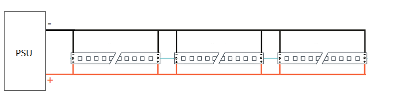
Ooh, nice diagram, @zranger1!

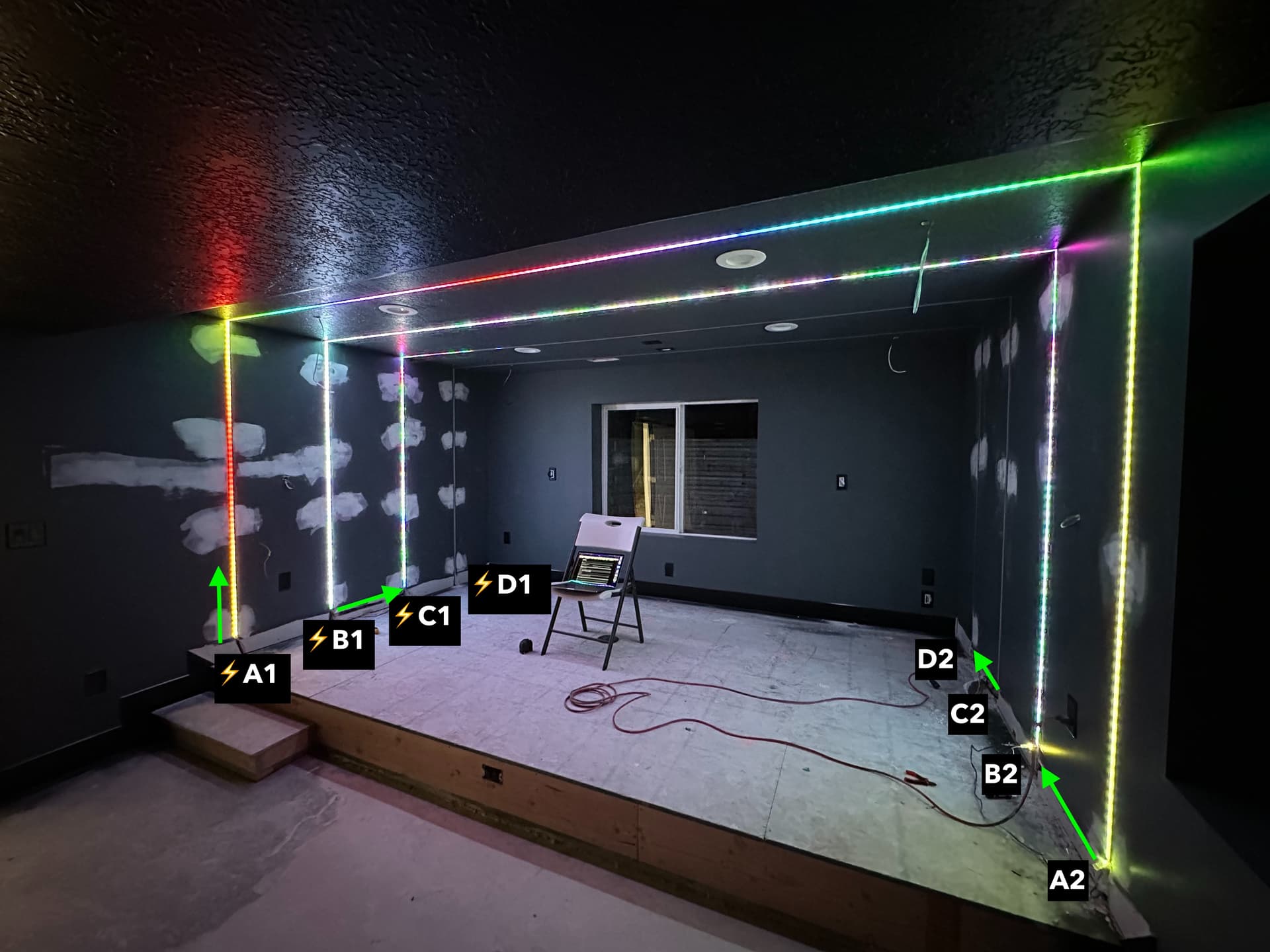
Yes! This is likely to have a very positive impact on your install! Props to Wizard for guessing this might be the case on a call we had yesterday, and sorry I just assumed ground was connected at A2-B2 and C2-D2.

Since different LEDs can be drawing different amounts of current (and thus dropping different amounts of voltage along the copper traces, including the ground trace), this means that the reference ground is discontinuous at A2 vs B2. The data line at the first pixel of B2 only knows what is low or high by having something to compare it to, and it compares it to ground.

Let’s say the A segment is supposed to be very bright. While the power rails are perhaps 0 and 5 V right where power is connected, by the time we get to the end of the strip, it might be that ground is actually up at 1 V, and VDD is now down at 4 V. This is probably still enough to power and control that final pixel. The data signal as well will be 1V for a data 0 (relative to the supply’s ground) or 4V for a HIGH (data of 1).

Now let’s pretend that the B segment is supposed to be all off, except for the first pixel right at B2. Since there’s minimal current bing drawn, there’s minimal voltage being dropped along those positive Vdd and negative Ground rails on the strips. The voltage at B2, relative to supply ground, is still very close to 0 and 5 V.

If only the data line is connected, and not the ground, the first pixel’s input at B2 is seeing 1 V for a LOW - that’s a fairly indeterminate value when it’s expecting to compare that input to it’s own 0 V ground.

Start with joining power rails wherever data is being passed as zranger1 suggested, then head to the rest of my list!


@zranger1 I’ve always read this as well, but on the art car, we used a nice scope and saw some strange stuff. Granted it was on 5V SK9822s, and granted, they didn’t have local bypass caps like they should have… but we still saw some strange stuff. In addition to ripple on the rails, we saw high frequency attenuation where the leading edges of the “regenerated” data signals about 300 pixels (75ft) in were looking smoother, like an exponential curve. At other times, we saw overshoot-then-dampen oscillation behavior. We also saw data and clock phase shifts relative to each other. I read that some of this is normal, that some pixels intentionally delay clock so that data is sampled further into the smoothed data state transitions, but it seemed extreme. I wish my S-domain fundamentals were better.

If anyone’s ever come across a practical guide to diagnosing SPI transmission line problems in the 500 KHz - 5 MHz range, I’d love to read up in depth!

It’s not exactly what you’re asking for but thought you might find this article interesting, in case you hadn’t already seen in before: Why APA102 LEDs Have Trouble At 24 MHz

1 Like

I think Paul’s experiment would be interesting to reproduce with sk9822 LEDs.

Yes, as far as I know, the clock and data signals are regenerated from each pixel, but they very well may be both 1) regenerated independently, carrying over any phase error, and 2) still slightly unbalanced such that they introduce small phase error each pixel.

That’s not true for ws281x LEDs and clones, which use a single data line. These regenerate the timing of the pulses as well, but operate at fixed data rates.

In any event, 24mhz is a pretty crazy high speed to drive those at! There’s little benefit with PB beyond 4mhz, except in some niche applications that would already have low pixel counts like high speed POV.

Thank you all for engaging with this. I’ve tried some of the suggestions here and so far, my first attempt from the pictures above has still been the most successful.
I reconfigured as suggested so the ground wire snaked through the chain and ran parallel to the data and had the 12v line coming in at A1, B2, C1 and D2. Only Track A worked in that scenario, though occasionally the first pixel of Track B would flicker a bit.
Yesterday, my output expander board arrived so I hooked that up, removed all connections between the tracks and have power and data feeding to points A1, B2, C1, and D2. Track A still works like a charm, Track C again lights up for the first third of the way, and track B and D are totally dark. I measured power output at the ends of the lines and it’s all quite strong. I don’t think that’s the issue.
Really really really trying to avoid rewiring since all of the drywall is new and the paint is fresh.
So, I have some of those RS485 transceivers coming tomorrow and will give those a shot. Don’t really know what I’m doing with them, but I’m sure there are answers here or elsewhere I can find.
Anything else I’m overlooking? Thanks again for all of the help and ideas so far. I’m learning a lot!

Completely dark? I would expect flickering of some sort if there was a transmission distance issue. Dark could indicate some other problem.

I would run the PB over directly, with a known good port configuration that works for the A strip, and test each of the other strips at their data input side.

Are you sure the strip data propagation directions are correct? It could be that you need to connect A2 to B1, B2 to C1 etc. An easy mistake to have made…

Wow. Impeccable timing. You sent that message just as I was going to bed after having fixed it!
Turns out there were two unrelated problems — a segment of the LED strips in track three was bad, which is why it was flickering and not lighting up the whole way. That was a red herring for me — making me think that that was a symptom of the whole problem, so I was poking and digging for the wrong thing. @DaveGadgeteer you are indeed right, the electrician did install the strips all going the same direction even though I asked for them zigzagged. He just installed the data line in a zigzag apparently not understanding the directionality of the strips. The strips were also installed inside diffuser tracks, so I couldn’t see the strips themselves. If tracks A and C had lit up fully, I think it would have been an easy thing to diagnose but I got thrown off by the half-lit track C. So in the end it was a good thing I needed to order the output expander because that’s the only way I’d have gotten it to work in this configuration. Thanks so much for all of the painstaking help everyone. You’re a kind and selfless bunch. Final pics coming soon.

6 Likes

This topic was automatically closed 120 days after the last reply. New replies are no longer allowed.