Does anyone have any references for a data booster for long runs? I installed some 2812 LED’s under a camper and controlling with Pixelblaze. Both sides have 32 feet each. I injected power halfway and at the end of each side. They are working, just a bit “glitchy” at times and the Pixelblaze IP controller isn’t responding very well either, such as won’t load the pattern animations or load at all sometimes. TIA!
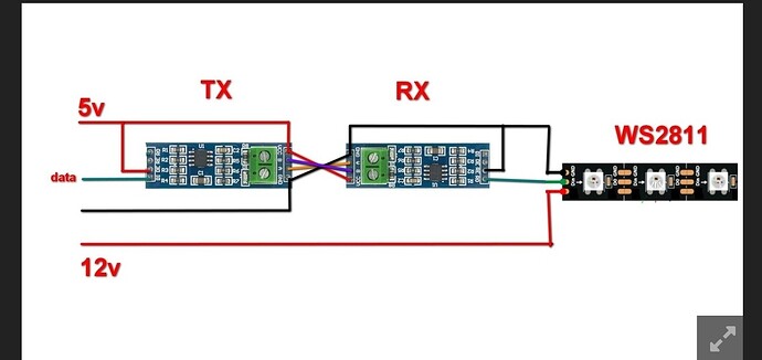
If you can install a pixel half way, thats one way to boost the signal. Another is to convert it into a differential signal, which can travel much further and has much better interference handling. Something like this can work:
https://www.amazon.com/Max485-Chip-RS-485-Module-Raspberry/dp/B00NIOLNAG
You’ll need one on each end, one set to send and one to receive. Could be used to install an output expander remotely too if you need multiple strips.
Perfect! With those, hiw would they be wired in? As far as the A & B terminals?
So the A and B are best when on a twister pair (ethernet cables work), run both from the sender to the receiver. Straight cable should work fine for the distances you have if you dont have twisted pair. You’ll also need at least GND. Power could be remote if that’s easier.
Yes if you want to use single 5V PS for the entire setup.
However it is better to use dedicated PS on both sides:
- 5V Ps on the TX side for the PB and Tx Transceiver
- 12V PS on the Rx side for the LED Strip plus small 12V-to-5v downconverter for the the Rx Transceiver.
This way you will need only twisted pair between AB Terminals.
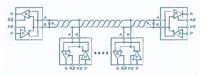
Also regardless of final power scheme you will need a 120 ohm termination resistors on both sides, on the Tx Transceiver pull-up DE, RE pins to the 5V via 2K-5K resistor and on the Rx Transceiver connect DE, RE pins to the GND.
Note: all the required resistors could be already on the board.
Perfect! Thank you so much!
@wizard how would you wire with a PB in the middle? Could you still control both side separately without a return wire?
With PB in the middle and no return wire, you would need an Output Expander.
I am working on a two-sided quarterstaff with a pico+6axis and I can’t have a return wire because the Fibonacci64 Micro HDR doesn’t have output. So far, I have wired it together to send the same signal in both directions … but I can drive an expander from a pico+6axis, right @wizard ?
Thanks for asking this question @john1! My quarterstaff can now be as I initially imagined it, presuming I can make a space for the expander. @JasonCoon I might just forgive you for the absence of output ![]()
The module PCBs I linked above incorporate those. R7 is the termination resistor. There are 10K pull up resistors for all the signal and config pins, so you can leave them on the transmit side and GND them on the receiver side (without 2-5K resistors).
Adding to
If you want to control them independently, you’d want an output expander. The expander could be on EITHER the PB side, or the far end. RS485 doesn’t like branches, but taps are OK. Still, probably easier to run two pair with the pair of transmitters fed off the data line from PB and having independent wiring to either side. When sending output expander data this way you could have a bus or multiple runs of expanders with different addresses and have several outputs at the far end run over the long distance line.
If you are OK mirroring the data, you can do that without output expanders, but still probably want two pair of tx/rx.
One Tx and multiple Rx on the same RS485 bus is OK. However it must not be any stabs and termination resistors must be only at the end points. Another words, for the mirroring one Tx in a middle (no termination resistor) and two Rx at the ends (with termination resistors) will do the job.
This topic was automatically closed 120 days after the last reply. New replies are no longer allowed.

