Data/clock signal cable for long run (20m) between PB and first pixel

Hi there,

I am using a PixelBlaze to drive about 1000 SK9822 pixels (100ft/30m of strips) for a deck lighting project. The 5Vdc power cables have been run already for power injection. The PixelBlaze is about 60-70ft (20m) away from the first pixel. I know it should be closer, but I put the PB in the same enclosure as the 5Vdc power supply, and given the layout of my garage, I was limited to where I could put it.

I bought a spool of 100ft (30m) of 18AWG stranded hookup wire for the data and clock signals. In my house, I tested the setup and was able to perfectly drive a single 5m strip with the 100ft of data/clock wire still on the spool. Great! So I unspooled the wire to install outside, and it doesnā€™t work. Iā€™m guessing the wire being on a spool did some black magic stuff that mitigated any interference/capacitance issues that enabled PB to work.

I know Iā€™m pushing the limits of things, but what kind of cable would be best for me to use to try to get this to work? Iā€™m guessing some sort of shielded twisted pair would be best, maybe a Cat6/7 cable? If I try this out, whatā€™s the best way to use the pairs to best help the data and clock signals get from the PB to the LED strip to minimize interference?

Iā€™m thinking of using two pairs, one for the signal and one for the clock. Connect data and clock to a solid color (blue/green) of a pair, and then connect the second pair wire (white) and drain to the DC negative as a reference.

Any thoughts?

Thanks :slight_smile:

Hi! Welcome back.

Have a look at these two threads which pretty much confirm your instincts.

Use two pair: GND+DAT and GND+CLK. If that still doesnā€™t work, the differential transceiver should.

Hi @jeff, thanks! I just ordered a STP cable, so Iā€™ll know later this week if this works :slight_smile: Fingers crossed!

@kavefish,
For runs that long I definitely recommend a differential signal, and you might want galvanic isolation as well.

The lengths of the data + clock becomes important as these have to arrive at the same time, and different lengths can cause small delays that push the 2 signals out of phase from each other, even with a differential signal.

An output expander uses a single data line though, and could be placed at the far-end and provide data+clock, so youā€™d only need a single differential pair.

1 Like

Thanks @wizard. Iā€™m going to give the STP a shot first, and maybe to to reroute it to make it a bit shorter as a second shot, then look at going to differential on the twisted pair.

Iā€™m looking at the Sparkfun RS-485 breakout board referenced in the threads @jeff linked above, and am a bit confused on the setup. Iā€™m guessing I would need four of these boards? Two next to the PB for data/clock and two at the LED strip to receive those signals. I get where the RS-485 output is, but not sure where the wire from the PB would go. Guess I need to study the schematic a bit more.

Yes, 4 total. I think how it works is the DAT and CLK from Pixelblaze would each be connected to the ā€œdata inā€ line on the datasheet, which is labeled ā€œRX-Iā€ and ā€œDIā€ on the pdf schematic.

buy an output expander, at that rate, youā€™ll be happier you did.

All of the differential RS485 chips Iā€™m seeing are half-duplex transceivers - they can transmit or receive (not simultaneously) on their A and B input/outputs. Youā€™ll need to pull a pin high or low on either end to set it to output or input mode, and will only be using half of each transceivers functionality since this will be one-way communication.

An output expander will mean 1 data line and thus 1 pair, and only 2 transceivers: one to transmit, one to receive the serial data. The downside is that youā€™ll be limited to 800 pixels and 800KHz bit rates on the output with the current firmware (when WS2812 isnā€™t used, it is technically possible to use other data rates). I didnā€™t realize you had 1000 pixels, so that does complicate it slightly.

You could split your 1000 pixels up across 2 channels on a single expander, but then youā€™d have data + clock running quite a distance from the expander to reach both, unless you ran your differential data to the mid point, and wire the strips with data direction going outward from that. With data originating from the middle, your indexes wouldnā€™t be linear anymore, and would need extra code to appear seamlessly with most 1D patterns.

RS485 is bus capable, so another option would be to use 2 receiving transceivers + expanders reading from the same pair, and run the differential pair to the start and to the midpoint. Your data+clocks will be short, total bandwidth pretty good, and pixel indexes can be linear.

I run 1440 pixels in my garden.

The wire to the first pixel is about 40ft (goes through the wall to controller indoors).

I used cat 5 UTP. One side of a pair connected to 5V, the other for clock or data. So two pairs used.

I did build a line driver and impedance matching circuit as well, but my initial installation (5 years ago) wasnā€™t using a Pixelblaze, so Iā€™m not sure if itā€™s still needed.

I did have to drop the frequency down to 4MHz, as pixels at the far end of the strip would start glitching at higher frequencies (these are APA102C strips).

So no differential transmitters or anything needed for 40ft or so.

Hi @Nick_W, thanks for the input. Iā€™m roughly 50% longer distance, so fingers crossed Iā€™ll have similar fortune as you.

Iā€™m still waiting for Amazon to deliver the SFTP cable I ordered a couple of days after my initial postā€¦ They dropped the ball, well, more likely the shipping carrier; it sat stuck ā€˜waiting to deliverā€™ about 3 hours away for 1.5 weeks. They finally agreed to ship another one, pending delivery tomorrow!

@wizard There are driver chips with dual tx or rx only, if you want to save some space. They are RS-422, which has the same electrical characteristics of RS-485 but is defined as one-way or one-to-many communication.

SN75157 dual driver
SN75158 dual receiver

And these are some of the few options still available in the 8-pin DIP package!

Well, I did have some success finally!

Using two pairs and grounding the shield, drain, and unused wire for each pair at each end, I was able to get things working with a 100ft SFTP cable after reducing the clock speed to 1MHz. I could get away with 2MHz if I reduced the number of LEDs.

With 1000 LEDs I was getting frame rates of 20-25fps. I have a shiny new PB3 waiting to be installed, so am hoping with the ESP32 thatā€™ll increase. I had low FPS with WLED on an ESP8266, and swapping it out with an ESP32, I had zero issues with speed; everything was buttery smooth.

In my control box, Iā€™m also going to have another microcontroller running WLED so that I can switch between the two using a relay. WLED doesnā€™t make it easy to change the clock speed like PB in its settings, so Iā€™ll need to do some investigating to see if and how I can do that.

All that being said, Iā€™m thinking about building another box to separate my power supply and the LED drivers. This will let me get the PB closer to the LED strips. Iā€™m not sure why I didnā€™t think of that at first, but as long as I have a good WiFi signal there, it should be doable, and I should be able to get my data/clock cable length down to less than about 8 feet.

Given what @Nick_W said about glitching at the far end of the strip, Iā€™m wondering if Iā€™ll run into that issue at 1MHz. Even more of a reason for me to consider relocating the PB closer to the start of the LED strips.

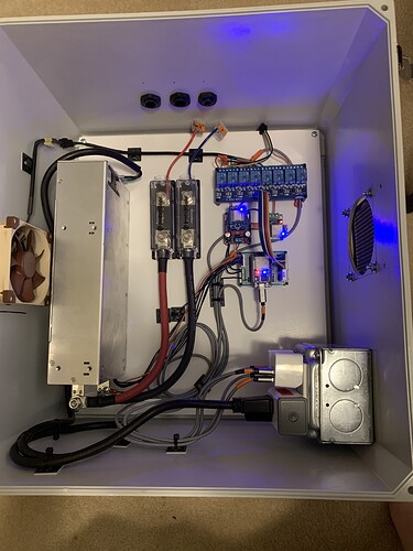
Hereā€™s my original box with 150A power supply, PixelBlaze, WLED controller, relay board, and an ESP32 to control the relays, fan, and 5Vdc power supply output. The box is a bit deeper than I needed, but it worked well. Itā€™s a shame I might pull out the PB, as I liked having everything in one box. Now that the box is installed in my garage, the small wires coming out of the fuse blocks have been replaced with the appropriate size wire. With 90A fuses, that tiny wire would be the fuse! :slight_smile:

3 Likes

Glad you got it working. Did you build an impedance matching network? Two in line 100Ohm resistors, and two 15pF capacitors to ground.

Makes a difference if the pb doesnā€™t have impedance matching built in. I can run 1440 pixels at 4MHz this way.

Also OMG a 150A PSU! I run two 12V 20A PSUā€™s to give 24V@20A, then out in the garden at each strip I convert 24V to 5V with a buck converter.

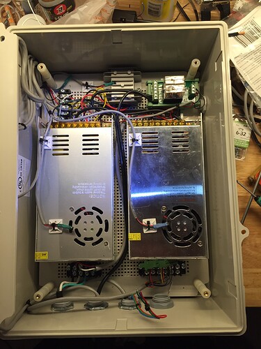
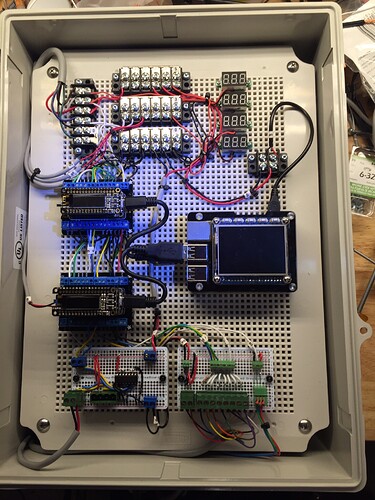
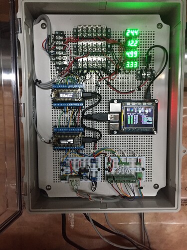
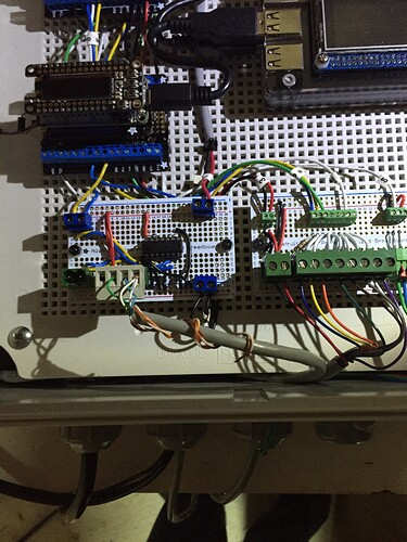
Here are some picks of the current rig. I plan to switch in a pb3 in the same way that you do, as itā€™s very hard to reprogram the M0ā€™s in place.

You can see the UTP connected in the last pic. The chip is the line driver/level shifter to generate 5V signals from 3.3V.

5 Likes

This is a nice looking build. @Nick_W where do you buy your box and fitted perforated board?

I think they were from mouser.

There are optional air vents on the side of the box as well, or itā€™s sealed.

Iā€™ll have to checkā€¦

1 Like

Ok they were these:
https://www.mouser.ca/ProductDetail/563-NBE-10567

And this
https://www.mouser.ca/ProductDetail/563-NBX-10987-PL

Took a while to find the order, I built it in 2016 - still working just fine!

I have a smaller box, just the same, but 6A 12V PSU and using a single ARM M3 controlling the deck lights.

1 Like