I did a dumb. Stacked screw terminals on top of 8 ch driver on top of PixelBlaze, then soldered screw terminals to PixelBlaze. Screw terminals = strips work fine. Soldered all the led plugs to 8 ch driver, they work not so much. 8ch driver is not soldered to anything. Cant desolder the 4 pins to unstick anything. Solder braid no help. Any advice?
Have a picture? Will help understand how it’s wired.
When trying expander outputs, was PB configured with output expander as type and a board added with some channels? Got a screen shot of the settings page?
ok missed this part. Definitly a hardware issue. works fine if I hold it just right, but the connection is loose. Set it down and the lights turn off. Just need to either disassemble somehow or add more solder?
So what’s the proper method for soldering the 8ch driver to the pixelblaze?
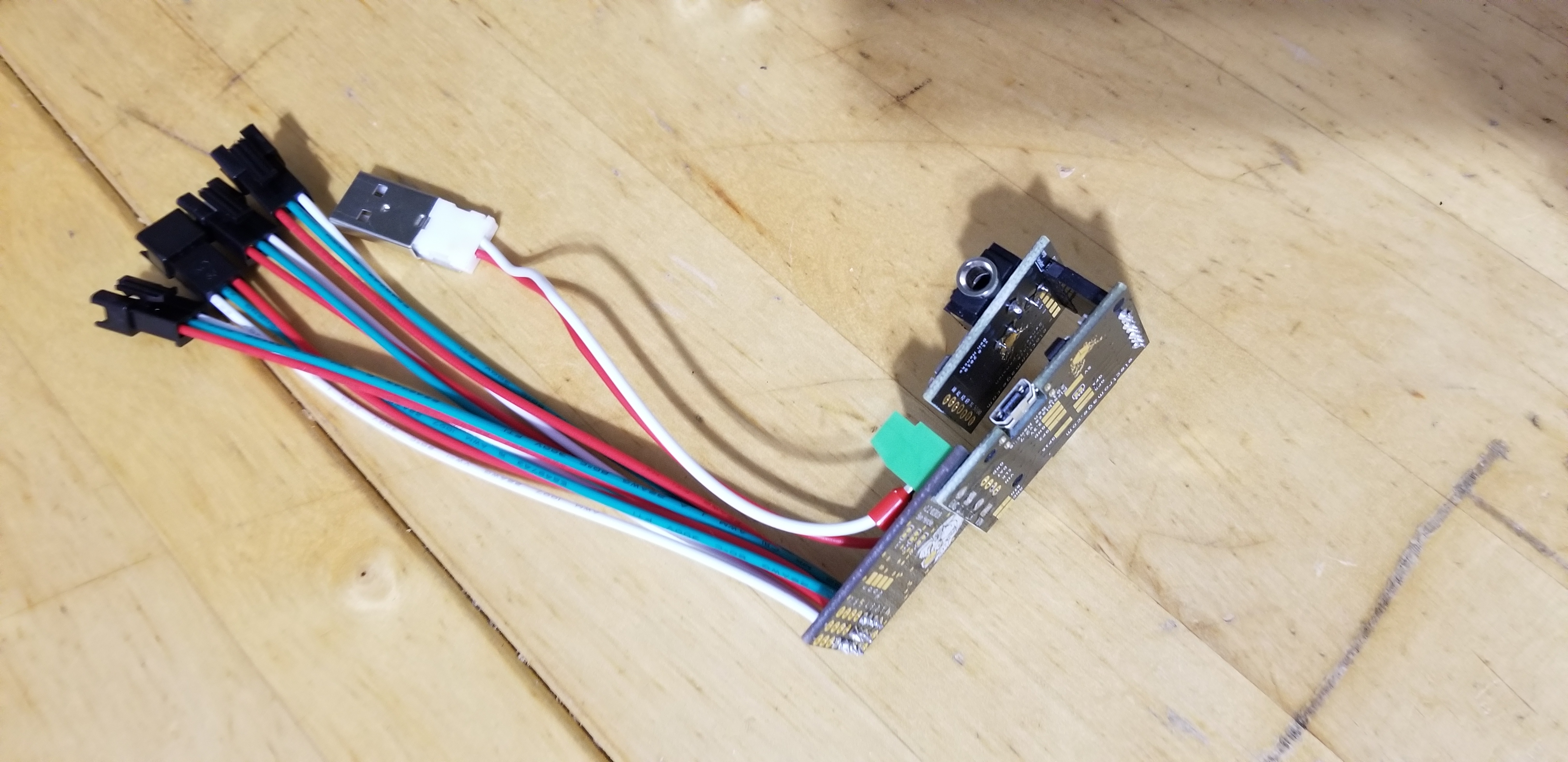
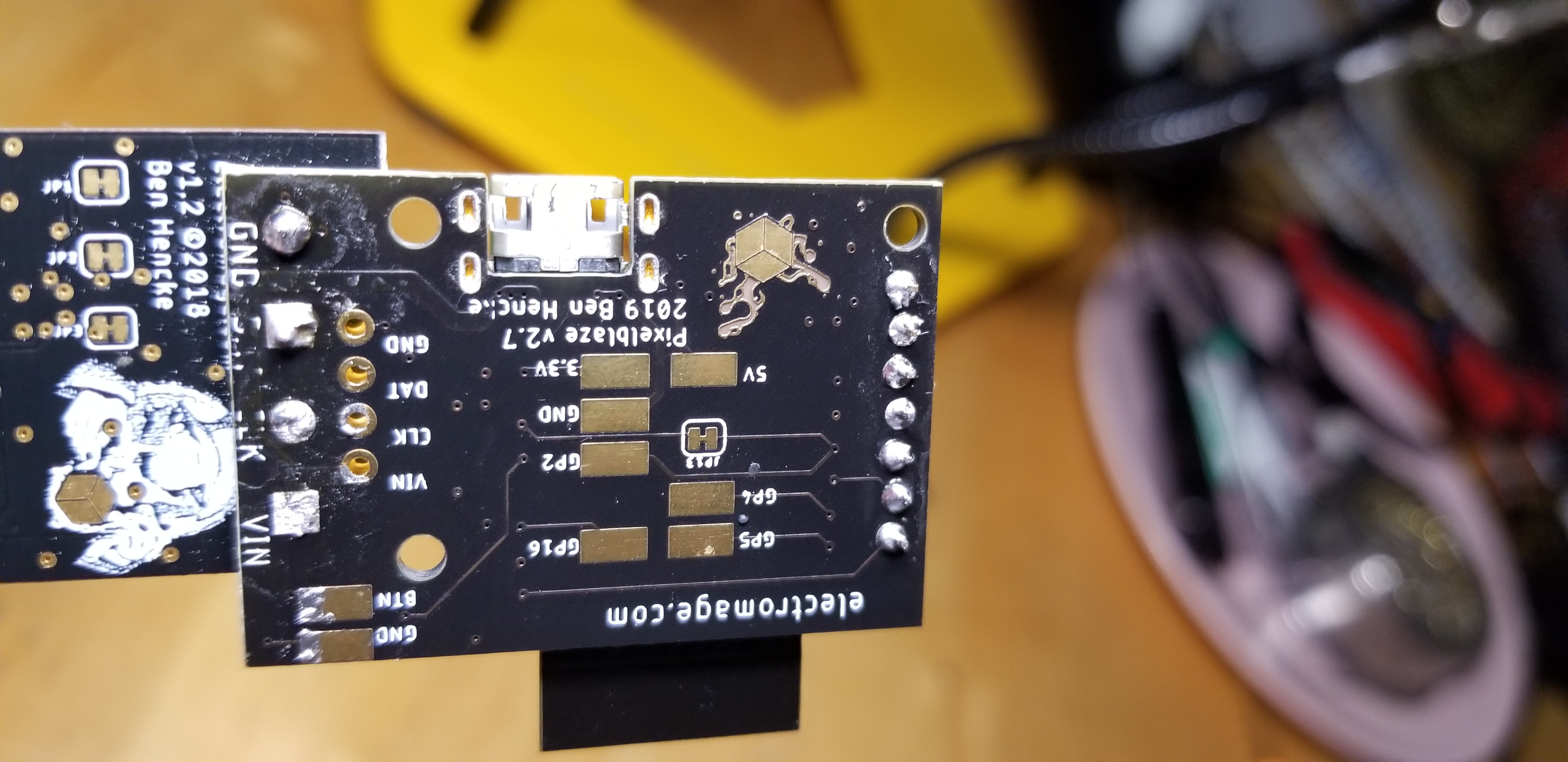
In the picture you’ll see from top to bottom (1) the green screw terminals with power lines screwed in, then (2) the 8 channel driver, not soldered to anything, then (3) the PizelBlaze which is soldered to the pins of the green screw terminals (1). When I plug everything in the LEDs don’t turn on. If I hold the PixelBlaze and the 8ch driver, and twist them just right the pins connect and all the LEDs turn on, but once I let go the LEDs go dark again.
I’ve tried pouring more solder down the pins but that doesn’t penetrate to the middle board. There’s 4 more through holes that are almost aligned, am I supposed to use those? If I put 4 pins through them the LEDs will turn on, but again I have to hold them perfectly. And the way it’s stacked those through holes are covered by the screw terminals on the other side.
You can mount it like that, but to do so you’d want to solder the screw terminal to the expander first, then solder PB to the remaining stubs. That way both are soldered solidly.
If you don’t need the screw terminals, you can stack them and solder together with bits of wire or pin headers. The 4 smaller pins work well for that (and you can do those first). Of course you can also have screw terminals on both boards, keeping them separate, and run some wire between them but that takes a little more space.
For your specific setup in future assemblies, I wouldn’t use the screw terminal, and instead solder the boards directly (with bits of wire or headers), then solder your power supply to the output expander near the outputs.
You might be able to wick solder to the middle board with some flux and heat. If you have liquid flux, you could try working some between the boards and applying heat, the solder might pull in to the hole and get to the inner board.
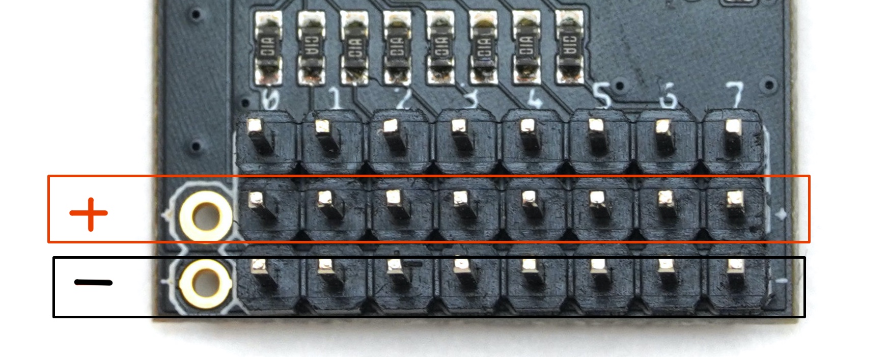
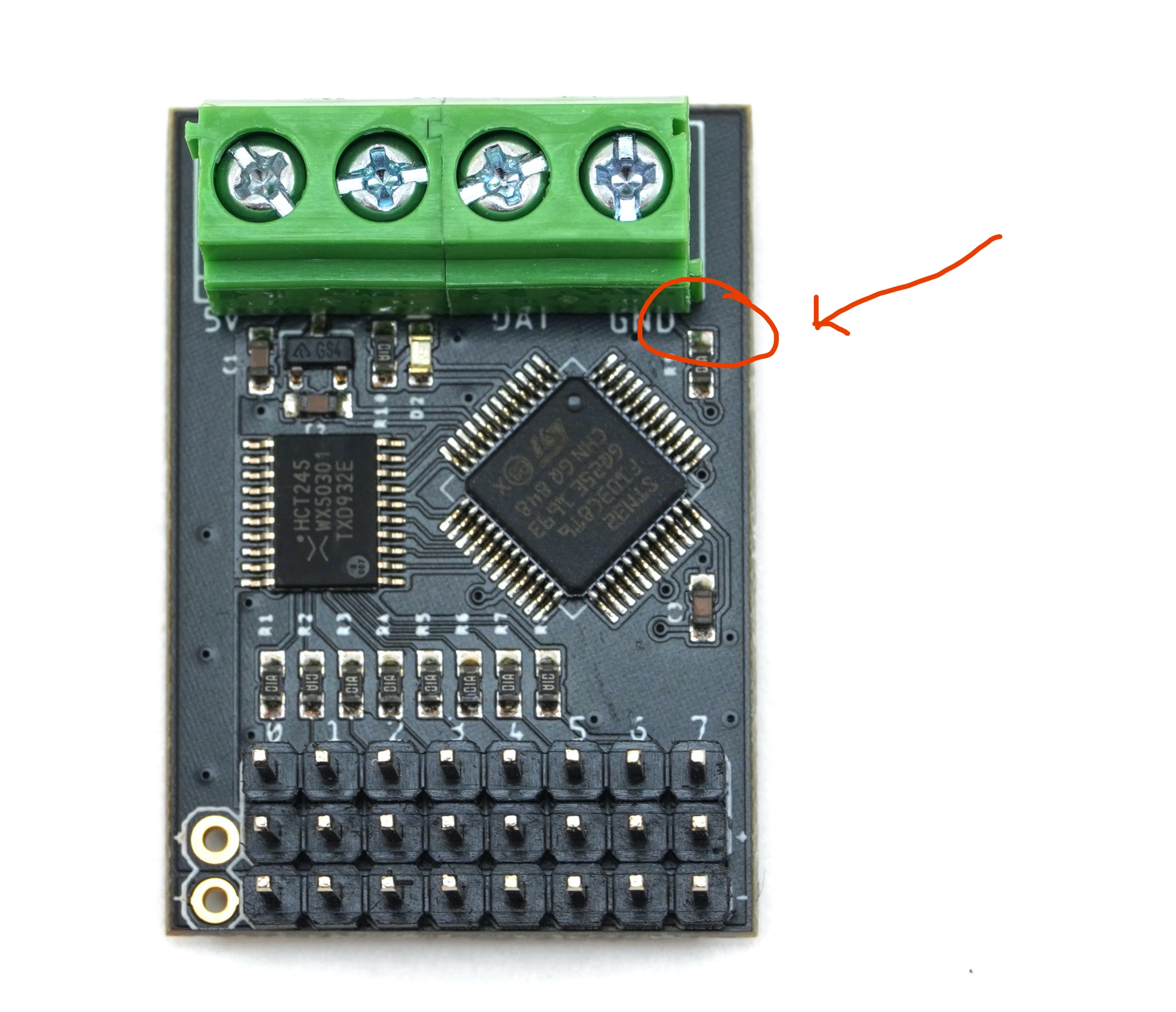
Other option would be to bodge them together. Bring wire from VIN, GND, and DAT on the visible underside to the expander board. GND and 5V are available to the left of the outputs. Its small, but DAT can be soldered to the resistor here. You can aim for the top, but don’t worry if you accidentally remove it or solder to both sides, you can bridge it with solder and it would work just as well for this.
Otherwise, removing the screw terminals will be slow… Sometimes you can get the iron on 2 pins, gently pry one side a mm or so, switch to the other side, and repeat. Some would recommend solder wick and/or a solder sucker, but I’ve never had much luck with those. You have to be careful not to force things or it could lift traces off of the PCB.
If all else fails, you can cut away the terminal tops. This can be tricky to avoid damaging the boards. Sometimes a flush cutter can nibble away at the plastic and metal, but again be careful not to pry upward from the PCB or the traces could lift.
Okay I was able to get it working by putting a 4 pin header from below and lots of solder. It can still be manipulated out of alignment with lots of pressure so it wont work for prod but the prototype is working.