sorry for the double topic, i’ve been lurking for a while but i’m still blocking on these points so it’s time for me to ask for help…
I’m using PB on a wearable with WS2812C (low consumption/luminosity LED) and WS2812B.
I struggle to have it work at very low luminosity: the target i need corresponds basically to the first increment of the luminosity slider from zero).
At this level, my LED can’t display enough colors: i have 8 colors (each led is either on at minimum setting or off)
If i want to be able to generate smoother gradients/more colors, i need to increase luminosity which becomes annoying for people around me (designed for dancefloors).
I’ve been trying to stick white tape on the LED, but it’s not very clean or reliable (easy to unstick), as well as white paint (does not look clean and i’m not so sure about heat).
I saw in a Youtube video that APA101 LED strips allow lower luminosity control: is it true ? I’d like to avoid to use 4 contact LED strips instead of 3 (much more soldering for me).
Any advice to have nice color gradients at very low luminosity ?
I feel like congratulating you for leveling up to the point we all reach at some stage where we start to grapple with this!
Pixelblaze was, in a way, designed for this problem. It was one of the first controllers to support the 4-wire (SK9822) LEDs. These have 5 extra bits for overall brightness so they can divide the lowest possible brightness of a WS2812 into 32 dimmer levels. That’s why gradients and dim patterns look so good on them!
If you really don’t want to use 4-wire, you’re left with the following options (which can also be applied to 4-wire LEDs):
Excruciating effort to hand tune your low values to least-bad
Use a diffuser that greatly attenuates the brightness, like the popular black LED acrylic from TAP plastics. You’ll need to run the overall pattern brighter then, which wastes battery, but the dimmer fades can still be better.
Switch to a WS2812 in a different package size, which usually consume less current and also output less light. In wearables, the fairy dots with stranded (not solid) wires are popular for this. You can get RGB LEDs in as small as 1.5x1.5 mm packages. Look for “1515” style LEDs. The common ones you’re probably using now are “5050”s.
I hope you join us with 25% more soldering and see why Pixelblaze is so amazing in HDR (SK9822).
There’s one more bad option: temporal dithering. To get “50% brightness”, turn the LED on only every 2nd frame. I would elaborate on how to do this, but like I said, it’s a bad option
I tried to display only half of the frames but it’s not effective at all on WS2812b. At higher luminosity it’s creating an ugly flicker, and at low luminosity it does not change anything.
I guess the only solution for me would be 33% more soldering… Not easy considering I’m already having space issues due to the wires…
I have done wearables in the past. I find that getting the connections solid is such a hassle. If you’re married to using strips, the apa102’s look so so much better for this stuff.
The bead leds are way easier to work with on fabric, but finding ones with less than 2 inches between leds is neigh impossible.
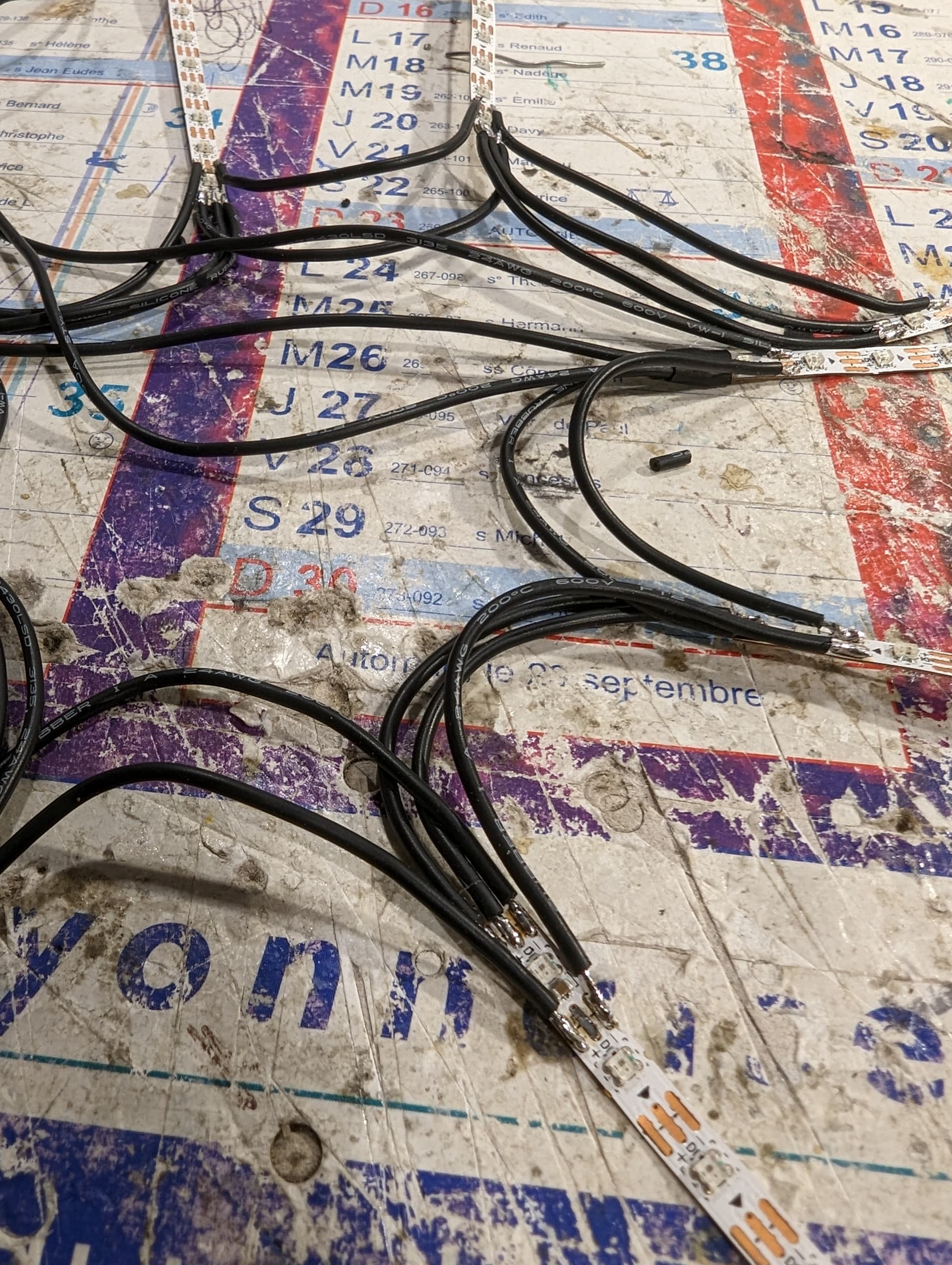
Can you share a few photos? I’m curious how you’re setting things up, and maybe I can provide some help for things that have worked well for me in the past!
Basically i’m working on a LED fan, so there’s a lot of movement on the cables, and these cables create a thickness making it hard to close the fan, so even if APA102s help with luminosity, the addtionnal cable will probably make it impossible to close the fan (+additionnal work on strain relief).
I’ve been using 2 different kinds of LED strips for my tests, which have their own pros and cons:
Large enough to do strong soldering easily, especially 2 wires together (on +/-) because power supply is in parallel / Strong sticking
Way too bright at minimum brightness. Can’t stick acrylic plastic on it (too thick, can’t close the fan) / I applied white tape on the LED (ugly and weak but works) / Under-voltage (3.7V instead of 5V) helps a bit but this is making my whites yellow-ish and i’m not sure PixelBlaze will be stable on it, especially when battery gets drained.
WS2812C / 120 LED/m - 2020 type / 5mm strip (see photos)
Super small contacts = pain in the a*** to solder / need to use different contacts for the +/- / More expensive / Harder to do the strain relief
I’m really open to any kind of advice because it’s my first electronic/LED project and i think i defintely didn’t chose the easiest way ! By the way the PB looks impressive on it, can’t wait to show you videos of it (once it’s fully done).
Let me put it this way: I’m willing to rebuild any of my WS2812 pieces to get this:
The extra soldering is totally worth it in low light situations … in a dark space even 1% power can be too much and 100% might be good lighting for cleaning up after the party!
Haha many thanks for the advice @sorceror , i’ll definetely order a SK9822 for some tests, but as you can see luminosity is not the only technological issue i’m dealing with…
Maybe 2 addtionnal questions:
I assume the wiring is the same as WS2812 ? +5V/GND can be connected anywhere and Clock/Data must follow the LED order right ?
Any recomendations of cables you usually use for wearables ? My system pulls up to 3A on my supply, so i should (normally) use something like AWG22, but it seems overkill. Now I’m using silicone insulated (very flexible) AWG26 cable which seems to work fine, but the insultation is still pretty thick (1.4mm per cable…) which makes it hard to close the fan. An addtionnal cable will worsen this. There are up to 280 LED connected to the PB, but technically never more than 20-30 in parallel, so i’m not too worried about voltage drop. Do you think i could go much smaller, or are there thinner insulated (but still very flexible) cables recommended for wearables and miniature apps ?
@hololit - that looks like such a great project. ive done a few wearables and one thing i can tell you, it usually takes a few iterations before you end up with what you had in mind… its the journey not the destination, right??
thats a lot of movement (and flex) on the wiring and solder joints. especially if you’re closing and opening the fan a lot, so there’s a few immediate thoughts that come to mind.
instead of wiring the leds all in a single sequence, you can try splitting it up (so you have a single wire to each strip without any wire-to-wire connection to the next strip). that can be accomplished by using the port expander but given the size and design of the fan, the port expander might be bulky.
if you aren’t doing the ports, then i think you might be OK with running the return wire back down the fan and then back up to the next one instead of going directly across.
also as jeff said - a custom pcb design where both input and output pins are located at the same edge closest to the center of the fan would greatly simplify your wiring.
taking that idea a bit further, if you aren’t locked in that specific fan design, (or if you’re able to actually construct your own fan) you could try using hollow ribs (like hollow aluminum tubes) and run the wire through inside the ribs with some carefully drilled holes
but now thats got me thinking, if you could put the whole thing (strip and wiring) inside a hollow, translucent plastic extrusion (something like 11mm x 4mm inner) for each fan rib, then construct the fan fabric around it with appropriate slits for the light to shine through, then that would look pretty darn tidy.
the challenge would be finding that extrusion with all the characteristics you need, but i believe theres gotta be something out there
I was also looking at LED strings (instead of strips) but I can only find thin ones with WS2812 … there are things like https://nl.aliexpress.com/item/4000910681004.html but obviously way too thick!
Hello, thank you for your advices ! Technically i don’t really need to change my LED strips, they are flat enough. The challenge is the 3 (potentially 4) cables at the bottom that take too much thickness… And running them at the top would not be very nice looking…
So I have an addtionnal question: What size of cables should i use ?
I need to be able to support full power on the LED (to avoid destruction risk as i won’t necessarly be the user), so it would mean around 3A at 5V max…
From what i see on the AWG gauge, i would need AWG22 for this, which seems to me extremely overkill: the cables are massive (especially with the silicon isolant), and I’ve seen a lot of consumer grade objects using smaller cables for similar powers…
I tried with AWG26, so far so good, but is it risky ? Could i go all the way to AWG28 or AWG30 ?
Technically, the longest cable between the supply and the farthest LED strip is around 10cm
I have no more than 20-30 LED per strip (9 strips)
At full power i estimate i can’t run more than 30-45 minutes
I don’t really care if the cables become a bit hot at white 100% brightness. My concern is more of the cable melting, or fire hazard…
The data and clock lines can be a small as you like. For power, it depends on the current and the resistance of the wire. The resistance will cause power loss.
With 26 gauge, you have 40.81 ohms per 1000ft, or ~41 milliohms per foot. At 3A one foot will drop 0.122V, or 0.36 watts of power. Double that for the other power wire. With 10cm, about 4 inches, thats around 0.24W.
Of course that length isn’t carrying the whole load, by the time it gets to the end it’s only carrying enough to power the last bit.
I am looking at the photo again … and thinking that for power, maybe you could use flat speaker cable and attach it to the fabric. You could put it anywhere on the blades and play with which position allows it to fold best.
I received SK9822 strips (144 led/m) today!
Indeed colors look really better at minimum luminosity, but the luminosity itself is pretty much the same. Definitely an improvement for me for sure, but not sure I wanna go the 4 wires way !
On the other side, wierd stuff with the clock speed: when putting at the minimum (around 450 KHz if I remember well), everything goes fine, but if I move up to 4 MHz (or even 20 MHz), I have wierd glitches (some led flickering, or going full brightness). Not sure where it comes from or which setting I should use for this …
That’s normal. Not every system can handle super fast clocks, just pick one that is stable for you. Generally 2mhz is plenty fast unless you are doing persistence of vision stuff. Long wire runs work better at slower clock speeds.