Friends, I’m not trained in electronics (PhD is in Information Systems, I’m a programmer & biz prof), so I’m really green on power, etc. As I give PixelBlaze v3s to my PhysicalComputing students (also green), I want to share guidelines on project power / safety. I wrote up when I think is correct, then pumped it through AI for a language tightening & cleanup (yes, I know its flaws, but it’s usually a better editor than me).
I’d greatly appreciate it if knowledgeable folks could give this a quick read, recognizing that this is targeted at: undergraduates at all levels all majors, for nearly everyone this is their first exposure to electronic - there are no pre-reqs for this course, they may be making projects ranging from wearables to larger “animated fields” placed outside for a “Festival of Light”.
I’ll also likely share something in an intro video lesson (all my course lectures are “flipped class”) once I’m confident I have the right info for newbies.
Thanks so much!
John
https://bit.ly/powering-pixelblaze-projects
Nice write up! A few suggestions:
For beginners, it’s going to be safest to just specify 60mA per LED and call it a day. I’d only use the 20mA true average in a situation where someone experienced will avoid a typo in the Pixelblaze IDE that could cause full white, and while applying a brightness limit in Settings is reliable, that wouldn’t protect from wiring mistakes that can cause data like noise that might also result in >33% of max average draw. Another example; if a student thinks “ok, for my project I only need a single color but across all LEDs at once” - red would draw 20mA per LED but yellow will draw 40mA per since red and green diodes would both be on at full intensity.
It might be clearest to specify a total number of LEDs that can be used with USB power, and you need to subtract about 200mA for the controller itself. Following my own rule above and our spec, (1800-200)/60 = 27 LEDs.
Note that the ubiquitous JST connectors on strips are only rated for 3A max and will heat up at their practical max of 5-7A. Also DC barrel jacks are officially rated for 5A max, though you see them all the time on power supplies up to 15A (certain manufactures with custom enhancements to lower the overall contact resistance can get close to 15A, but the connector can also still get quite hot). In your position as a prof, best to recommend soldering or WAGO style connectors for anything over 3A. Also you should make mention of fusing - since you can’t know if they’ll all be choosing high quality Class 2 supplies with overcurrent protection, best to say that the positive line of any power supply must use an inline fuse close to the supply if the power supply can exceed 5A or so.
You can’t overdo it with the max amperage rating like you mention, but you can sure make the consequences of an accidental short a lot higher with a higher capacity supply.
You mention “Use thicker wire (18–20 AWG or thicker) for high-current runs” but I’m commonly selecting between 10-18 AWG to combat voltage drop, so I guess it all depends on your definition of high current. Maybe the best practical guidance you could give is to require someone show their work with an ampacity chart and voltage drop calculator for > some number of LEDs. My go-to is American Wire Gauge Chart and AWG Electrical Current Load Limits table with ampacities, wire sizes, skin depth frequencies and wire breaking strength for ampacity - 20AWG will handle 11A safely but will drop the 1.3V into glitch territory after only 2.5ft of a 2 conductor pair. Many voltage drop calculators only start at 14AWG and larger, this one lets you input 20AWG: Wire Size & Voltage Drop Calculator | GRE Alpha
Otherwise it’s a super solid guide!
This is all such fantastic advice, Jeff. Thanks a ton for going through this. I’ve learned a lot from your post. Will be sure to make updates. Kind of you to reply. Cheers!
Good write-up ![]()
My best friend when experimenting with LED power supply estimates is a USB power meter. It will show you exactly how many V, A and W the LEDs are sucking for each pattern. With that you can test to see how many Amps different brightness and patterns take and adjust either the brightness/patterns or the power supply.
I did this for my burner bike to make sure it stayed within the USB powerbank limits and to make sure my powerbank lasted as long as possible.
Cheers
PS. I have this one, but most similar will work fine: Eversame 2 in 1 Type C USB Tester Color Screen LCD Digital Multimeter, USB C Voltage Current Voltmeter Amp Volt Ammeter Detector USB Cable Charger Indicator DC3.6-30V/0-5.1A - Amazon.com
Thx for the specific product rec. Just ordered one. Cheers!
Thanks again to all who offer advice. A few more questions:
When running 60 of these lights, even off a 10 amp power supply, I noticed that a pattern that seemed to flash near all bright lights froze the pixelblaze.
https://www.aliexpress.us/item/3256804490683280.html
When I look at these wires, it seems that they’re thinner than wires in other lights, like the ones below, that seemed to run the same pattern, fine, with 100 lights.
The power supply’s barrel jack was connected to the end power / ground of these lights, and the PixelBlaze was on the DIN end, with power, data, ground all screwed into the PBs terminal blocks. 1) what is likely causing this glitch and 2) is there something I can do to make using these lights more robust?
I’m also trying to figure out how to configure multiple lights with multiple power injection points but one PixelBlaze driver. Let’s say I inject 5v10a every 200 LEDs. Can do this:
- At the end of the 200 LED run, break off power & ground & connect to a barrel jack - so for 400 LEDs I’d have two power supplies in the middle and end.
- Continue to have the signal wire connecting all lights.
- Have the PixelBlaze connected to Power, DIN, Ground at the DIN point of the LED chain.
- Do I need to do anything to tie together the ground connections of the various power supplies? Is there anything else recommended to help signaling?
It’d be good to know various scenarios where one needs to be concerned. For example, some students are going to want to try to “make a field light up” by stringing LEDs across a field around a statue, maybe in a 50ft x 50ft “Matrix” layout.
Others will want to have lights more densely packed to create things like an archway people could walk under while animating.
Still others might want to put together several 16x16 matrices to create much larger rectangles that can be animated.
Thanks for experienced help & guidance!
There’s a few possible causes. Given that PB is resetting, it experienced a brownout, where the voltage available to the chip dropped below a threshold. Ideally, the PB will get a constant 5V.
- Resistance in the wires and connectors causes voltage drop that scales with current.
- The power supply might not be able to maintain voltage at it’s rated current. Common in cheap supplies.
- The transient response of the power supply might be poor. That is, it is too slow to respond to an increase current load and the voltage drops temporarily. You’d probably need an oscilloscope to see it. I’ve seen this more in low cost DC-DC buck converter modules (and one of the reason’s I made the Mini Buck).
If I’m reading that right, you are powering the LEDs on the far side, furthest from the connection to the Pixelblaze, and PB is powered through it’s connection to the LEDs? The current of the LEDs, plus the PB, has to run across all that length of wire and resistance and is going to add up and voltage drop will be quite high.
You want PB as close to your power source as feasible. Its very common to apply power to an LED strip/string and backfeed PB via the output connector, however this should be done by connecting power on the end close to the PB, on the input side, usually only a few inches of wire.
Tips for power injection:
- Keep PB as close to the power supply as possible. Don’t power PB through LED string/strips.
- Always prefer to power the input side of your LEDs. This gives them the cleanest GND reference for data interpretation. You can power the end/output side too, but don’t skip the input side.
- Always connect GND along with data, even if you break power into zones, even if GND is connected at the power supplies. Especially if you have a separate power source for PB. Data is relative to GND. If your GND rises due to voltage drop (yes, it works both ways), then your data signal is also going to drop relative to that GND.
- Most, but not all strings/strips are generally designed to be able to handle the current required to power that segment at full power, but not much more.
Note: When we talk about GND, it’s is not necessarily earth ground. It’s the negative side of your power supply, which are often isolated for safety.
Thanks so much, Wizard. Does this diagram illustrate how things might go if I need to inject power at multiple points? Grounds from the power terminal block back to the LED and across strips, power isolated on the components its powering, signal connecting all LEDs back to the PB.
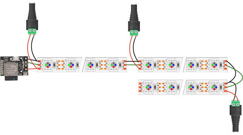
That looks right to me.
Another thing to add: When I’m driving 12V LEDs, I have a 5V supply for the PB and a 12V for the LEDs, with shared GND. When it makes sense (e.g. in an installation which is plugged in or large) with 5V LEDs you could consider having separate 5V supplies. A random old phone charger could power the PB and then a chunkier one for whatever the LEDs need.
I’m not sure how this interacts with the idea of a ‘rising’ ground, but it seems like power isolation always helps.
Yes!
Isolating them is good for making fault zones, so one problem doesn’t cascade. When you have fuses (short circuit protection) for each injection run, or scale up power with separate power supplies, you want isolated zones.
If you are injecting from the same power supply with fairly low wattage, you can usually leave the positives connected too. Fine for small systems, like what you might get with 10A. It won’t hurt to isolate them though.
@jeff 's advice here is dramatically more conservative that I tend to recommend for people just using 5v USB power, especially for wearables, if they’re willing to be careful. Jeff – you have 27 LEDs for USB power as a conservative max, and I’m currently sitting here designing a wearable that’ll be about 350 LEDs off USB power, and it will be totally fine – although I recommend beginners stick to <200 LEDs off USB.
I think the community does beginners a disservice with the 60mA answer – especially with the pebble LEDs which have a lower peak than that. I’ve been recommending this beginner guide for… well, since long before I discovered PixelBlaze, and I think it is required reading for people who want to start with just USB power.
This also matched what @Gallaugher has in his current draft, “144 LEDs × 0.02A × 0.3 (30% brightness) ≈ 0.86A → Runs on a good phone charger or USB battery.” which I think is a pretty good starting point for beginners.
In my own projects I take real measurements (and use ratios like what you describe) and fuse it if needed, but here we have a professor guiding students who will be using a variety of LEDs and we have no control over the wire gauge and flammability of what they’re embedding the LEDs in (like, pillows are not uncommon).
Plus, as beginners, someone’s definitely going to accidentally run them at full white and mix up which pixelblaze IP they’re on the web interface for while changing global brightness. Fuses take a lot of time to blow, too (and usually only blow after a long time above their rated current - see the fuse curves). We have no idea how students will decide to power things (LiPo, cheap PS that doesn’t meet spec or have internal overcurrent protection).
So if you have to make a blanket recommendation and liability is on the line, the harm is that they have too few LEDs or oversize their power supply, which is pretty appropriate for beginners. You and I may be willing to just exceed our USB port’s current rating, or trust the internal resistance of the PCB traces to reduce the voltage and current draw and we’ve seen it doesn’t spark a fire, but I’m looking out for the lawsuit.
Totally fair! And I agree with you on what the most conservative answer is, and the most conservative answer is usually the right starting point, especially when it’s partially “your” forum, and it could be construed as official advice.
But correct me if I’m wrong, but if you power the system via USB-A → Micro-USB → PixelBlaze → LEDs (powering the LEDs via the PixelBlaze itself), the PixelBlaze itself will turn off and provide your overcurrent protection without lighting things on fire – you may damage the PixelBlaze, but you won’t start a fire with that wiring path (legal caveat: you can always start a fire by being dumb enough with electronics, but in most situations…).
I also think that commercial 5v USB-A power sources (e.g. battery packs…) are less high risk than any of the higher voltage higher power things you often bring to the table – because everything fails a lot more gracefully when working at 5v off USB-A power than higher voltages, and bare LiPo supplies have a lot more complexity.
For other people reading this later – (100% that @jeff knows this already) – if you’re thinking “wait, I don’t want to get a multimeter, I don’t want to learn any fancy tools, I just want to know the power draw of my USB thing” – get a cheap USB power meter (random Amazon example that my order history says I have; it’s “fine”), and use it. They’re <$15 and a godsend for testing small scale projects like this.
P.S. – I’m trying to get a new LED shirt done for Oakland Autumn Lights in two weeks, and in testing I’m running all 391 LEDs off USB-A without power injection… but I’m being EXTREMELY conservative about everything you can possibly do to save power, and this is a generally bad idea you SHOULD NOT DO when teaching beginners…
That is not correct. Perhaps the usb port or cable will fry before causing worse damage but it is NOT a safety device. PB doesn’t have any circuitry to limit current, only parts with current rating limits.
Most usb power sources will quit after some limit, but that is also very dependent on the usb port, entirely outside of PB’s control.
And I learned something today! Thanks Wizard and Jeff as always.