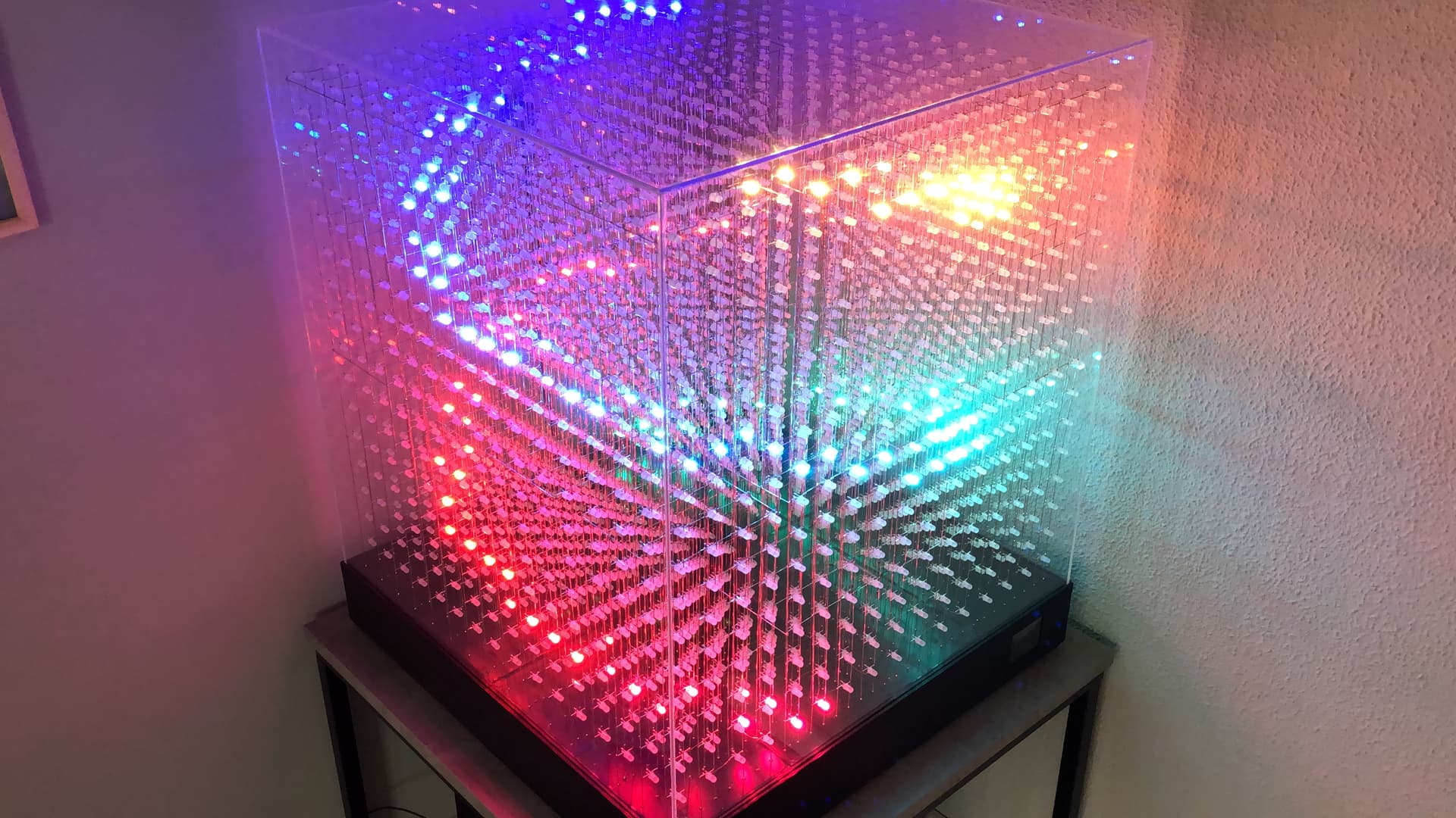
So my camera just does not work well when trying to film LED stuff but you folks get the idea.
Took about 100 hours, copious help from this forum at times and having to rebuild all the planes over again because the first brand of LEDs I bought were AWFUL and I decided to say screw it and just try again with a less terrible brand.
Moving on to screwing around with the coding which I am clueless on so I can only guess how many hours it’ll take. I used Bens code from one of my threads and at least figured out how to invert it so it’s at least mapped for the moment which is good because I did not understand the mapping tutorial at all. I don’t have a mind for this stuff so I think this is gonna be harder than building the thing but if I can dump 100 hours in to the physical part, I can at least dump a few in to figuring out some code.
I think I’d like to figure out how to make some waves first and go from there! Thanks for the help!
Awesome! Maybe we can help with mapping? Can you describe how they are wired (pictures and diagrams help). I’ve looked back at your last post but still not 25% sure how it works.
Do you have 4 independent columns? Are each 4x4 zigzag, then run to a layer above, and so on? Is each layer the same pattern or does it change?
Sure! So I ended up wiring it in a not smart way because I was just ready to be done with it. I should have run everything on the bottom or planned to have the planes match up but oh well. Gonna wait for the 16x16x16 to do it better.
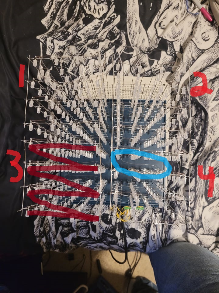
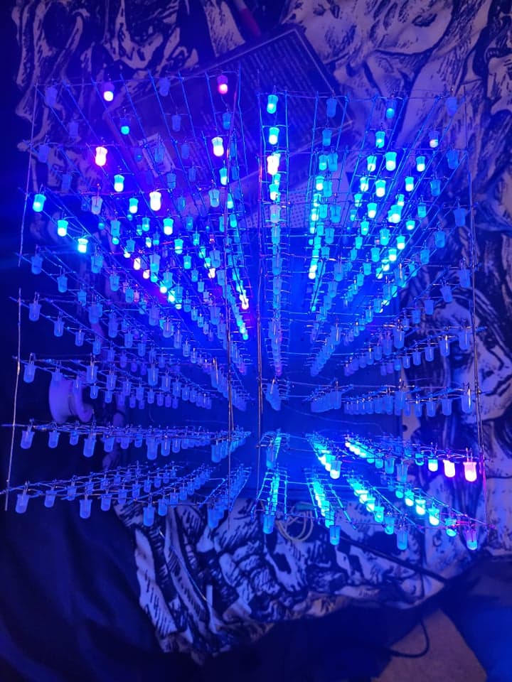
In the first pic you can see in the bottom left where the wire runs back to under the PCB to the PixelBlaze and it just runs like a snake to the bottom right of each plane before a jumper sends it back to the bottom left of the next plane behind it. 4 Planes per PCB just snaked to the back right corner. 128 LEDs per PCB. The numbers correspond to which channels I have the PCBs wired to on the PixelBlaze. The light blue circle just shows a clear shot of the jumper wire that connects each plane. Hope that helps!
That helps!
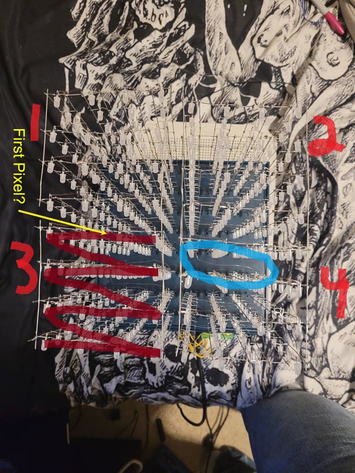
So I see from the data source, it first goes up (+z) , then one column over (+x), then turns around and goes down (-z). Or is that the back, so it would be opposite the photo: left (-x)? Repeat to cover 4 columns total (y, flipped too?). So the whole cube is made up of 8 heigh, 4 wide, 4 deep pillars, of which there are 4?
Looking at the second photo, does pillar number 1’s data start at the bottom left, like between 1 and 3?
Here’s a map, I think I have it right, but you can watch the dots move along in the mapper to see if thats following the wiring.
I added a bunch of comments so hopefully it’s easy to follow along and modify.
function (pixelCount) {
  var map = []

  function pillar(startX, startY) {

    //4 layers per pillar
    for (layer = 0; layer < 4; layer++) {
      //doing a whole layer, 4x8 pixels at a time
      for (i = 0; i < 4*8; i++) {

        //x moves once each 8 pixel column
        //x goes right to left, so it will look like this: 3, 2, 1, 0
        x = 3 - Math.floor(i / 8)

        //start with z going up, wrap back to zero every 8 pixels
        z = i % 8
        //now make z go downward on odd columns
        if (x % 2 == 1) //check for odd
          z = 7 - z //reverse direction

        //the y is going to change once per layer, going back to front
        y = 3 - layer

        //now put all the coordinates together, offsetting by this pillar
        //startX and startY
        map.push([x + startX, y + startY, z])
      }
    }
  }

  //since we've corrected the x,y so that pillars start at their front left
  //the first pillar is on the right front
  pillar(4,0)
  //second is left front
  pillar(0,0)
  //third is right back
  pillar(4,4)
  //fouth is left back
  pillar(0,4)

  return map
}
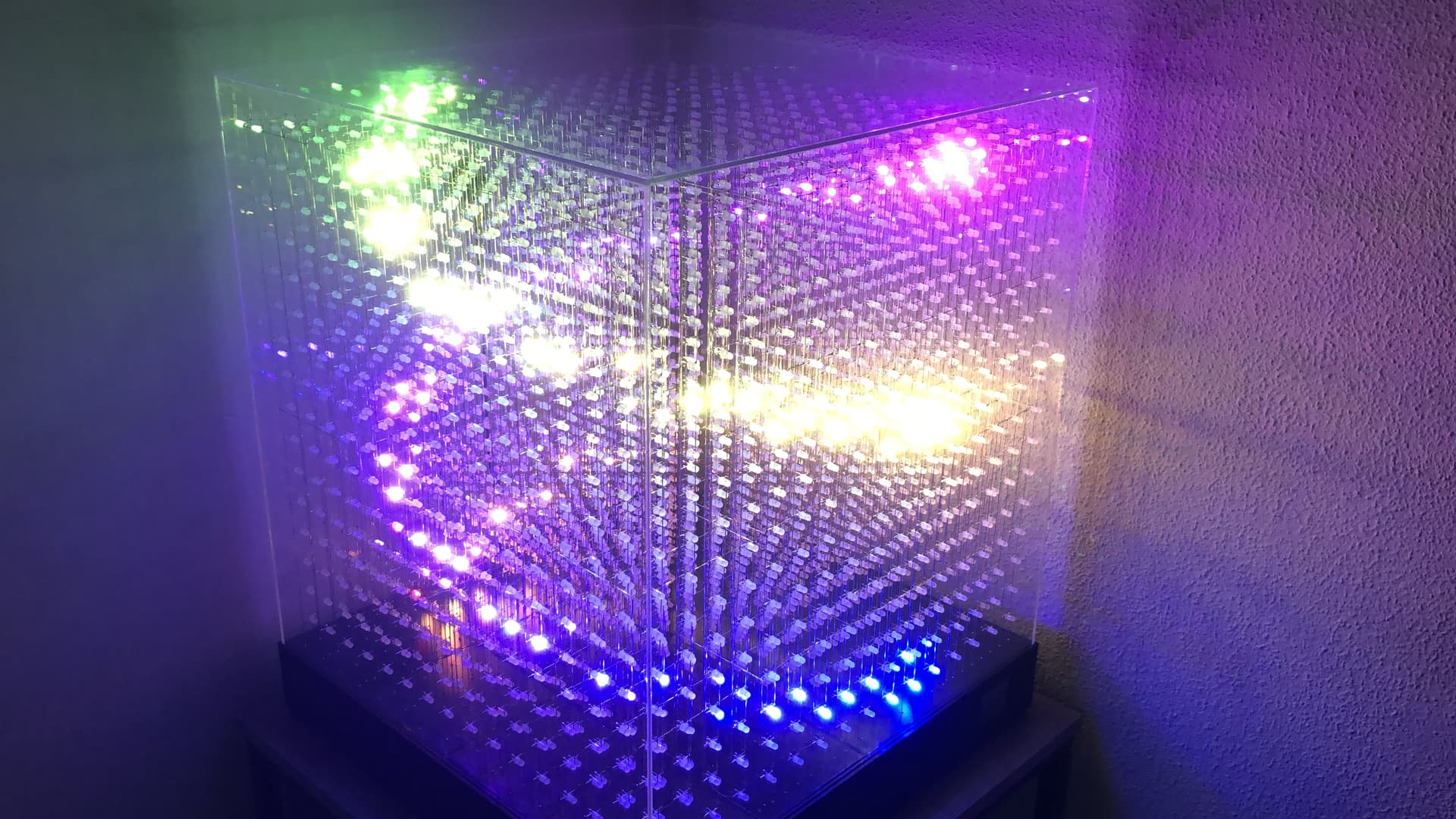
Holy crap thank you!!! And the mapping worked like a charm! Also there is enough in the code comments that I think I’m gonna be able to piece together some stuff with a bit of google-fu. Should probably figure out what Sin and the rest of the advanced math stuff means Anyways here’s how it looked after loading everything up!
Looking much better!
I think some of the pillars might be swapped or something with the zigzag isn’t 100%. Did the RGB XYZ sweep pattern match the example video?
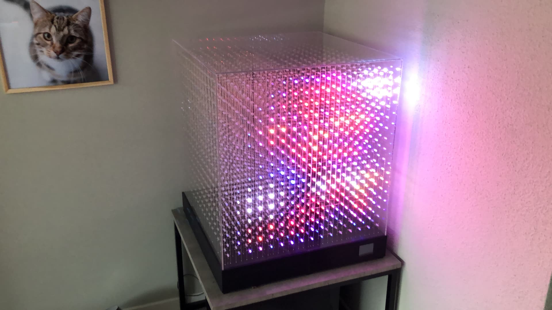
Sorry, concert night last night when I saw this message! So no it’s definitely not doing that pattern. The more I look at it, the more I realize it IS doing it but it’s doing it independently on each channel/PCB and not as a whole.
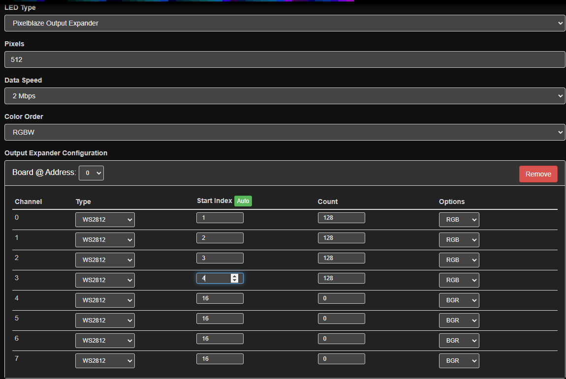
Which on that note, this is how I have the expander configured. Does this make a difference for the potential mapping?
Hey there! I am! I’m gonna take a break for a few to just focus on learning some basic programming so I can do some fun things with this one and if nothing else just get a handle on the coding.
Also need to do some prep work and get my guy to 3D print some stuff I didn’t bother with for the 8x8 like full sized jigs for both odds and evens, and a few more cutting jigs cause 512 took way longer than I though. 4000? Gonna bring in some help for that one lol. Also since we made a custom base for the 8x8, need to print the one you made.
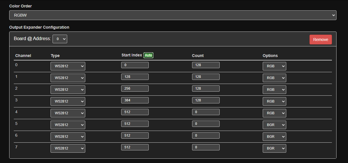
Ah, that would do it. The start index is the pixel index, not the channel index. Set your channel 0 start index to 0 (In PB everything is zero-indexed), and then click the Auto button and it will calculate the start Indexes for you. It starts filling out channel 1, using channel 0’s start index + count, and so on.
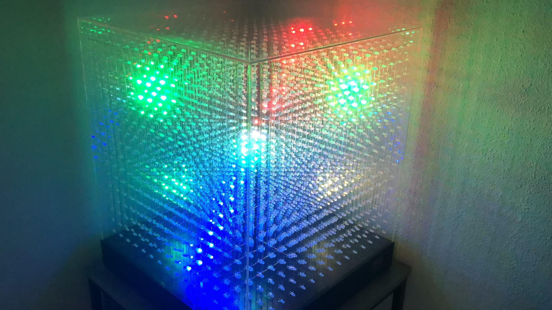
Ah, that indeed helped and it’s looking much closer to the sample video! Though now the 4th PCB for whatever reason isn’t working. I’m guessing it’s just a settings swap I need to adjust
Pretty nice pattern here. Maybe i’ll code in c++. How would the PB perform with 4096 leds? What frame rate is to expect? The teensy runs at 178fps but thats way overkill, but doesn’t hurt either