Hi there. I just got a pixelblaze to try from my friend, and I’m struggling to get any output from it. I’ve gone to increasingly simple setups. I’m currently just trying to get a single strip of ws2813s to connect to the pixelblaze, with or without the output expander. Settings are 100 brightness, 10 pixels, and I know all my parts work because Im coming from a working arduino setup (just using pixelblaze for wifi hopefully).
The only situation in which they work is when the pixelblaze is connected to my pc via microusb and then the strip is directly wired to the pixelblaze. When I use an external power supply (I’ve tried two different ones), there doesn’t seem to be any data output to the strip, even tho the pixelblaze is connected to wifi and fine.
I have checked:
electrical connections are solid with a multimeter (also simplified the circuit to the extreme)
Been banging my head on this for a bit, and strange that my friend didn’t have problems with it. Am I missing something obvious? Are 2813s not supported? Why do they work when connected to a computer?
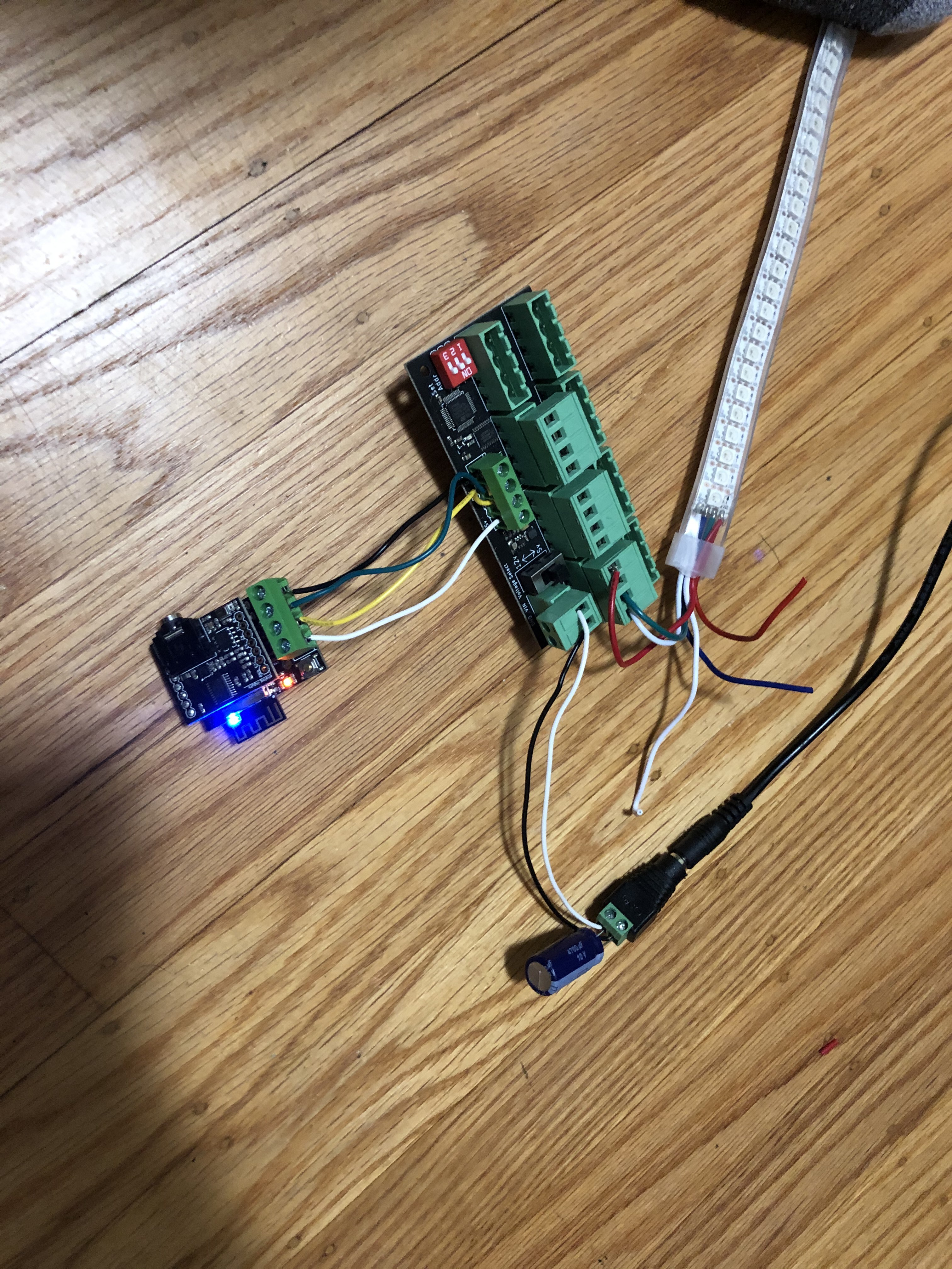
Here’s the base setup i’ve tried, with the expander and without (changing the settings accordingly…)
This is pretty mysterious. Might be a good one for the @wizard.
Right up front: I can’t explain why it would be working powered over the microusb, but not via two separate 5V power supplies, especially when the web interface is working.
What I did notice, which may not affect anything at all: We had a discussion about the 2815 recently where we saw it was recommended to ground the backup data in, which I think is your blue wire.
This shouldn’t matter at all, but when using the pro expander, it looks like you might have jumpered the data line into the clock of the pro expander. Just FYI, I think that’s NC.
Thanks for the reply. In this pic from the strip to the expander red is power, white is ground, green is data. I just double checked to verify but the green is going to the d0 pin, second from the left between the ground labeled pin and C6.
But even without the expander it doesn’t work, which is also strange when the strip is wired to the pixelblaze directly. Blue is the backup data pin, yeah best practice is supposed to ground it but i havent found it necessary when running arduino/pi. I just tried and no result anyway.
Thinking aloud here - I know you tested with a multimeter. As part of that, what kind of voltage are you seeing from your supplies when everything is connected?
Somehow, this seems to be fixed. Honestly, I have no idea what happened. I was writing out my reply to you - I went to verify voltage with my multimeter which was 5.3V and was going to say I know these power supplies work since Im coming from an existing arduino setup and just swapping the controller. Nothing while I was plugged in testing voltage.
When I was reading through my reply to you I look over one more time and suddenly its working, I didn’t touch it >_< no idea whats happening and if this issue will arise in the future again. Going to wire up a more complex system (three strips) and see if it can run them. I’ll triple check all the connections in case its some kind bad wire. Thanks for your help @jeff
Hi @poisionde,
Glad you got it working! I thought of a a few tips for future troubleshooting:
I believe that the WS2813 and similar LEDs with a backup data wire left floating can pick up random noise in some cases. They work by detecting signal on BI, and nothing on DI. Since these LEDs “latch” or draw based on idleness, the 2nd LED (where BI is routed to) might start picking up noise during one of those latch times, thinking the main data line has gone dead. Likewise, connecting both to the data signal could cause the 2nd LED to start using the data intended for the first since it will arrive before the first LED starts relaying data.
The Output Expanders have an orange status LED that will light up when it sees data addressed to it. If the LED is dark, it could be that it isn’t getting power, not getting data (or not getting output expander formatted data), or not getting data sent to the board address it is configured for (using switches on the pro, or cut traces on the smaller expander). Based on the photo, it should have been at address 0, but no light is on.
What you describe sounds like a loose connection perhaps. I know you verified these with a meter, but I figure I should mention some common problems with the screw terminals.
Cold solder joints can make intermitted connection. Since the screw terminal solder leads are thick, and the copper rings are often near large copper traces, these can take a few extra seconds to heat up. and for solder to flow properly. Hitting it with an iron and some flux can help.
Another fairly common issue with these screw terminals is getting enough stripped wire so that it’s clamping down on metal instead of the insulation. As far as I can see in the photos you are good there, but figured it worth mentioning.