In my project I connect some leds in parallel. Up until today I was getting data straight from PB and had no issues whatsoever. I connected the output expander, and now whenever I connect some leds in parallel in any of its outputs, I get flicker. It occurs only in the ones in parallel, the ones that are in series are fine unless they are connected downstream after the ones in parallel. Is that a matter of timing? Can anything be done to solve it? I’m using SK6812 btw.
Extra bit of information. My led strip is divided in 10-led pieces. In the beginning of each piece I’ve added a 10k resistor in the data line in order to be able to hot plug them. Could that cause the flicker? It doesn’t if I use the data line straight from PB.
@Petros,
10k on the receiving end? Both PB and the expander level shift to 5v and have a 100 ohm resistor before data is sent out. It sounds like the fan out (sharing data across multiple inputs) and extra lines is enough to modify some of the digital signal enough to flicker.
You could add a buffer IC, if you tie the input of a few buffers to the same signal, each of the buffers outputs can drive a number of LEDs in parallel, basically multiplying the number of things you can drive with a single output.
Other hacky options: You could use more outputs and configure them for the same pixels (though it calculates them twice), or add another expander with the same address to get another set of outputs.
Flicker persists regardless of the expander outputs used, I get it even when using one output. Would it make any difference if I lowered the resistors to 5k?
Would the buffer ic make any difference if it was placed directly at the expander output? There is no space in the led connectors, so it would be something like this: expander output, buffer, 10-20 leds in series, 3-way splitter to 30 leds(10 each), 10-20 in series, etc. I have no idea what to look for, so if you think such a setup would work, could you suggest an ic?
Is it maybe possible to use only 2 of the expander outputs, change the timing or any other similar trick? I’m looking at 300 pixels max, but given that many are in series, it would be more like 150.
Given that the setup worked great before I connected the expander, my understanding is that any sort of booster or buffer could be placed right at the output of the expander, regardless of how the leds are connected downstream, is that a correct assumption?
If it’s not working with the expander alone and directly to one of your LEDs, then maybe it’s a timing issue between the expander and that particular LED, or the 10K is enough to put it on the line between marginal and flickering.
Yes, to try a buffer that is where I would place it, but if it’s not working with a single LED then fan-out doesn’t seem to be the problem.
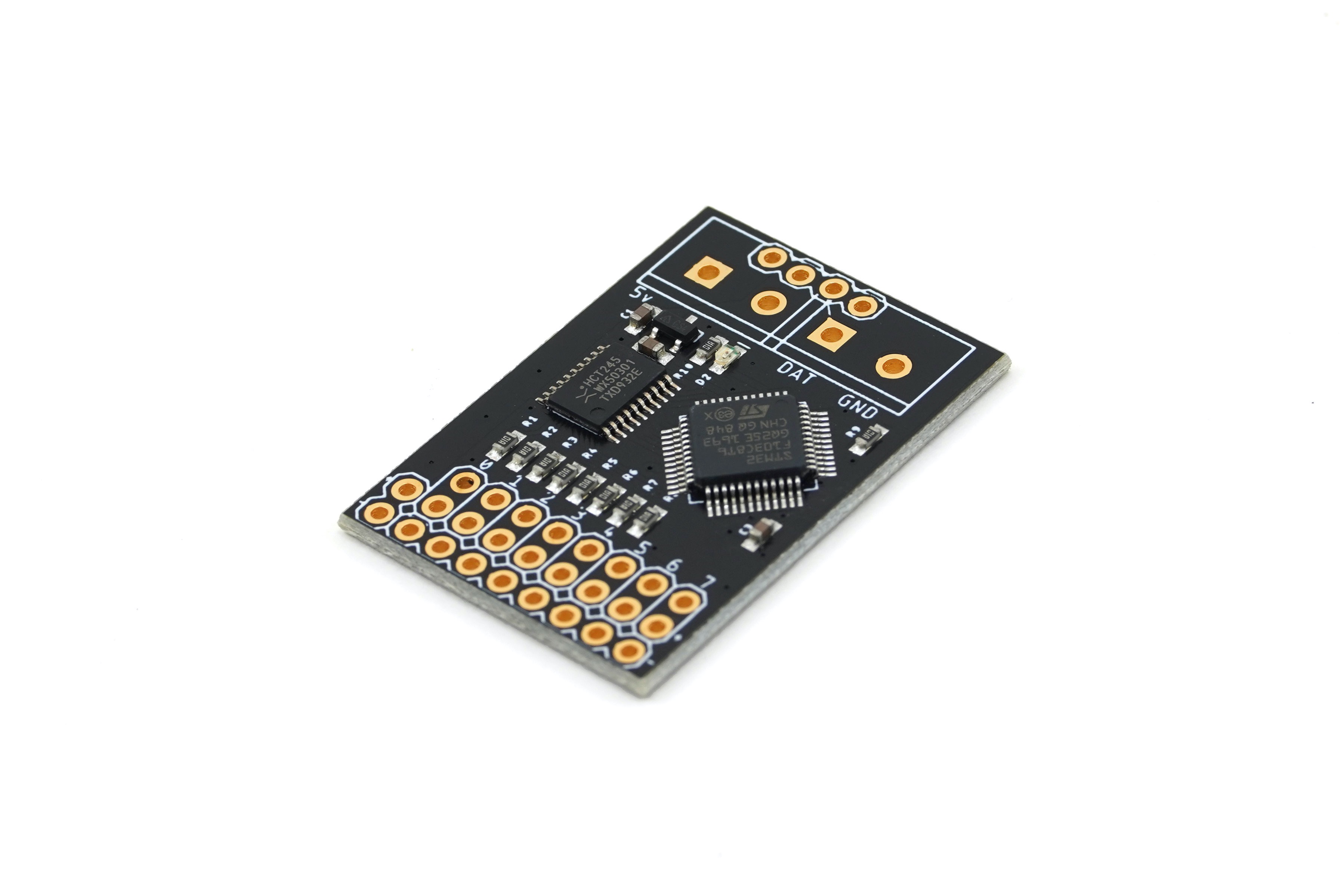
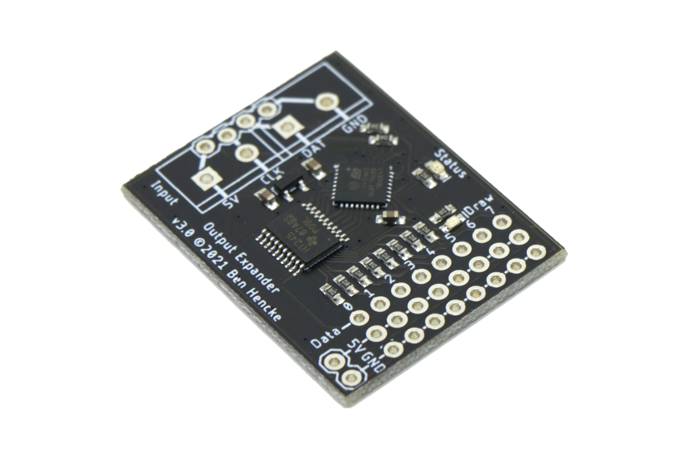
Are you using a V1, V2, or V3 expander? The timing on the expanders isn’t adjustable outside of reflashing with new code, unfortunately. Timing has been adjusted slightly over the versions. Most LEDs work fine, though I have seen one LED variant that worked marginally. That same LED would not work if driven from other WS2812s/clones, so it uses an incompatible timing. The V3 expanders have better timing tolerances (less variation) than previous versions owing to the new MCU.
Side story: The iffy LED variant was on some 8x8 panels I had bought. The QA on the panels was terrible. One panel had a mix of LED variants on the same panel (the small IC was different between them!) and the LEDs stopped working right at the change. One of the reasons I decided to make my own panels.
Another idea, perhaps worth a try just to see if it helps: you could use a single LED as a buffer. The LED will regenerate the timing, assuming it interprets the data properly right at the expander. If it doesn’t you have an incompatible LED type, though a V3 expander might work better.
The expander works fine with the less, as long as they are connected in series. Once I connect a couple of pieces(10 leds each) in parallel is where the flicker starts. I’m using SK6812 RGBW by BTF-LIGHTING. Given the nature of the project and the hot-swappable necessity, every 10-led piece has a 10k resistor regardless if I connect it in series or parallel.
I’m guessing(?) I have a v3 expander, I bought both PB and expander 6 months ago from Tindie.
The idea of placing a single LED to regenerate the data is definitely worth a try. I do wonder though, if the data is regenerated in every LED, isn’t that happening anyway? Or is it that since the output comes in contact first with a resistor and then with a LED it’s degraded already? When using PB’s output without the expander, I’ve successfully connected 6 strands in parallel btw.
If the LED solves it, I’d like to also try a buffer IC, could you please suggest one? I tried googling it but given my limited knowledge I didn’t come up with something useful.
A buffer is a digital logic gate that outputs what it sees. You can make a buffer with other types of gates, like a pair of inverters, an AND gate, pair of NAND gates, etc.
There are a zillion logic ICs with families and subfamilies:
See more info here:
I’d see what you can easily get, try for the 74HCT family (though many others would work. You can also use one of the level-shifters from sparkfun or adafruit, which are buffers that can take different voltages for input and outputs (like 3V to 5V), but should run just fine with a single voltage.
I’m using 4 outputs from the expander so a 74HCT08 AND gate seems to be what I need. What happens to the expander outputs when they are disabled in the gui? Do I need to add a pull down resistor in every input of the gate? I read they should never float.
You might have luck with a v3 expander as well, they have tighter timing tolerances so there would be more margin to work within with the fan-out.
The outputs for a channel with no pixels stays low, you don’t need a pull down. But you won’t be connecting any of your inputs from the 74HCT08 to the 4 unused ports anyway. To make a buffer from an AND gate, either tie both inputs together from the same signal, or tie one to positive and one to the input signal. With those 4 AND gates you will get 4 buffers with each input(s) connected to each of the active channels on the expander, with nothing left over.
If the buffer doesn’t do the trick, do you know if I can find V3 in the EU? I paid quite a lot for shipping/customs to get everything from the states last time:(
If the buffers don’t work out, I have a new low cost shipping option I could try, though I don’t know what kind of delivery times to expect.
You can also give Mouser a try. They have shipping options I don’t, though I imagine the customs fees/tax is similar. Mouser are showing only 2 in stock, and while I’ll be shipping them some more stock soon, it can take a while for them to process it into their stock system.
(Note that Mouser photos show V2, but they are almost certainly shipping V3 since all of the V2s were sent out for the Crowd Supply campaign)
@wizard I’m resurrecting this thread as the flicker persists…
A short recap:
The light I’ve built is modular, and part of its charm is being able to hot-plug the bricks. While building it, I realized that on occasion the first pixel of a brick would get burned if hot plugged. I put a 10k resistor and solved it. This introduced flicker when using the output expander, but not if connected straight to PB. After your suggestion, I put a buffer IC in every expander output and solved it.
I found out later, that sometimes the last pixel of the output brick could get burned as well, so I removed the 10k resistor and put a 4.7k on each side(start&end), thinking that staying under 10k in total would not re-introduce the flicker, yet it’s back!
You had mentioned that expander V3 had more tolerance(I used V2), so I went ahead and got one, but I get the same results.
Any idea why adding 2 4.7k resistors is worse than one of 10k? I guess I could go for 2x3.2k and see what happens, but it’s quite an undertaking, the bricks are not easy to open as everything is glued together(yes, I should have thoroughly tested everything before putting them back together!), plus I don’t know if they are going to be enough, or if they’ll start get burned again.
Is there anything that can be changed in the output expander, a different firmware that would solve this? Is it a hardware limitation compared to PB that doesn’t have this issue? I’m using SK6812 btw.
Yes, it’s possible expander firmware could mitigate the issue, then again it might not depending on the cause of the issues. If the timing is just marginal, adjusting the timing in firmware might do the trick. If it’s signal reflections, it might work for some, and make others worse.
I would try 100 ohm resistors on the TX side. Generally you want to match the characteristic impedance of your transmission lines, and 100 ohms is a good middle value. It could be anywhere between 33 and 330 ohms.
It might also be power surges causing damage from hot plugging. ESD protection might also help on both sides.
When you say TX side, do you mean right after the expander, then in every input/output of the 10 led/strips? As in replace the existing 4.7k ones? I wonder how low they can go before the leds start getting burned again.
I have TVS diodes in every input in order to protect the 24v-5v downconverters, so that part is covered.
I’d be willing to flash the expander now that @zranger1 posted how to, but I have no clue what I’d need to change in the code. If it’s something simple and you could share it, please do!
The expander has a 100 ohm resistor built in, I mean on the output side of your modules.
You might want TVS diodes on the data lines, both input and outputs.
To change timing, change the CCR values here:
And for V3 boards, use the V3.x branch, similar location:
In both cases, the timer CCR is 1:1 with the MCU clock cycles. For V2 expanders that is 72MHz, for v3 it’s 80MHz.
So e.g. on v2 the zero bit time is 15 cycles long (time between CCR1 and CCR3) or about 208ns (this was mainly to account for high jitter on the STM32F103 bus). For V3 it’s 24 cycles or 300ns. That’s usually where the issues happen, but you can change the “stop bits” too which is where the one bit time comes from (time between CCR1 and CCR4).
I thought it wasn’t possible to add a tvs diode on the data line, I’ll get a few and give it a try-I guess I wouldn’t need the resistor as well in that case, correct? Then I’d have no issues with the timing anymore.
suppose it depends on the capacitance it might load the data with, check specs. There are also other ESD protection devices designed for high speed digital signals that could be used.