Help! Voltage regulator is overheating

I’m using a pixelblaze in a large project that’s going to a festival in 2 days and I ran into an issue that’s really stressing me out.

I was getting the system all set up to test out, and shortly after I supplied power, a component (U1, 63P) on the Pixelblaze released it’s magic smoke. I’m almost certain it’s the 3.3v regulator. Not exactly sure in what order I did things that caused it.

Fortunately, I have a friend with a PB that he’s lending me, but I’m running into the same issue and it’s really baffling me.

This time I plugged things in slowly and carefully with my finger on the regulator.

1 - supplied 5v power to full chain (w/o PB), checked voltage to make sure it stayed 5v.

2 - supplied 12v power to full chain (still w/o PB), except for the first board (no reason, I just forgot to wire it in)

3 - powered down, added PB, powered up. Everything looked good.

4 - Then I noticed the first driver wasn’t powered by 12v, so I fixed that.

5 - When I reconnected power, the regulator immediately got really hot, so I quickly disconnected power.

6 - started to disconnect everything while checking to see at what step the regulator would stop overheating when powered.

Now the regulator is overheating with nothing at all attached to the PB, just plugged into usb. Although it’s not heating nearly as fast.

Is the regulator compromised and will always overheat now?

Most importantly though, what caused the issue?

Some notes:
There are 53 drivers in the chain.
None of the LED strips were plugged in at the time.

Project schematic

PWM Driver board:

PWM IC Datasheet:
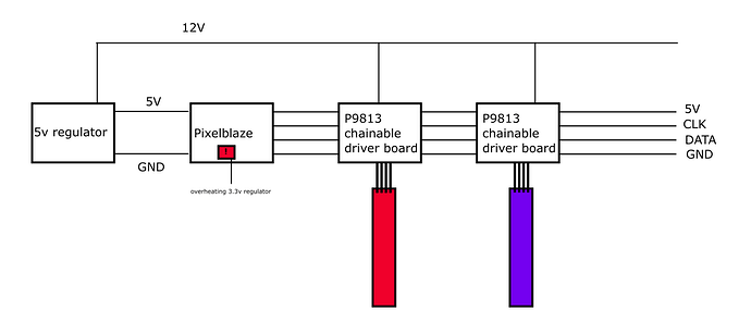
I just plugged in the PB (not connected to anything) and after about a minute the regulator fried itself… It continues to get really hot but there’s no blue light anymore.

Is there any way that the 12v is getting backfed to the PB across the 5v line? Are the LEDs 12v or 5? I wasn’t sure why the P9813s were getting both 5v and 12v, but I haven’t ever used the RGB led drivers, just the P9813 pixels (which I’d love to be able to use PB with, so how’d you do that?)

This definitely looks like >6v is making it to PB. The 3.3v regulator on PB is rated for 6v max, and feeding it 12v will definitely do damage. Can You verify that only 5v is making it to the power input pin?

The other common way to blow the regulator hooking up power with reverse polarity, but that doesn’t seem to be the case here.

I notice in your diagram, you have 4 wires from the 12v LED controllers, is that back-feeding into PB as pictured? I think you only want GND, DAT and CLK connected. I don’t see a 5v power on those controllers, just 5v data, so the 4 wire chain is probably 12v, which is probably fine for those modules (it looks like they bridge the power input to the 4 wire chainable interface), but not for PB.

If you are lucky, only the regulator is toast, and you can use an external 3.3v regulator fed into the expansion port to resurrect a PB with just a bad regulator. The regulator needs to be able to output >300ma for short periods to keep the ESP8266 happy. If you want to replace it and can do SMT soldering, its a AP2112K-3.3TRG1.