How many analog input pins are exposed on V3

I’m building a new project and need lots of analog inputs(more than 1+5 of V3 with sensor board). I remember seeing a post somewhere about a new revision of V3 with more pads on the back, but can’t find it now or remember if there was any mention of analog pins. Is that board out?

I know the answer already, but is there a way to connect more than one sensor board?

As at least 4 of the inputs will involve pots, could I use a trick like the one here for each pair?

Without multiplexing or any other trick like the above, I’d need a minimum of 12 inputs:)

Wow, interesting challenge.

First, about the number of analog input pins; The original v3 standard spec, under Features & Specifications, listed 9 GPIOs, 5 of which could be used as an A-to-D. This was a mistake as I believe only one (IO33) was actually available for A-to-D. The current listing lists 1 A-to-D pin, however, in November @wizard announced the v3.5 hardware, which restored access to 4 more analog inputs, for 5 total (edited for clarity based on Wizard’s clarification below). I can confirm the most recent batch I ordered was shipping HW v3.6 with all the extra breakout pads on the bottom.

With the Sensor Board, you’d have all the inputs you need: 5 analog there, plus 15 GPIO total on currently-shipping hardware v3.6.

Some other ideas and options for getting lots more IO into a Pixelblaze:

  1. Use the open hardware and software of the Sensor Expansion Board to make a version that could fill up the 32 audio frequency bin slots with analog sensor values instead. There’s a great recent post from ZRanger1 about how to get started on custom board stuff (he makes a custom output expander in that post, but it’s also applicable to a custom sensor board).
  2. You could, in-theory, multiplex multiple sensor expansion boards into a single Pixelblaze, but you’d need to be careful with timing. The sensor data is refreshed 40 times per second, and while I’ve had no problems or crashes hot-plugging sensor boards, you’d probably want to wait > 1/40th of a second after switching boards to trust the data. Mux chips are cheap.
  3. Many different on-off switches can be combined and read simultaneously off a single analog input with a specific resistor enabled by each switch. Imagine a voltage divider where three switches add together combinations of three different values: 1KΩ, 500Ω, and 250Ω. You can probably do something similar with potentiometers, but I imagine it becomes very sensitive to temperature drift and the A/D resolution.
  4. You might just make a separate A/D board with many inputs and focus on getting the data into Pixelblaze via websockets over WiFi.
1 Like

The currently shipping v3.6 boards added 6 GPIO pads: 39, 36 on the top; 17,16 on the left; 34, 35 on the right.

Of those: 34, 35 , 36, and 39 should all support analog inputs. Thats a total of 5 analog inputs on the V3.6 Standard hardware. GPIO 36 and 39 are input only, can can’t drive signals for output.

That gets you pretty close with 5 on the main board and 5 on the sensor board.

1 Like

It is indeed quite a challenge:)

I believe that Ben used ADC2’s analog GPIOs which conflicted with Wifi, that’s why he had to abandon that eventually. I’ll wait until he replies on this and gives me a number I like:)

I thought of that, wondered if PB expects 5 analog inputs(A0-A4) from the sensor board or if it could receive more, ie connect another board with more inputs, say A0-A9. Whichever the case, having to reprogram the sensor board or program a new board and feed the data to PB, is way beyond my coding knowledge.

This is pretty much what I want to do with some of the inputs. Here’s a brief of the project:

I’m doing a new version of my modular light for my children. A very crude version of the controller is this:

Screen Shot 2022-09-12 at 10.46.26 PM

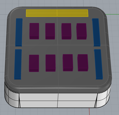
PB will have two outputs, each will be controlled by 2 sliders and 4 slots. Sliders control speed and expansion of pixels moving along the strip. I’m making little colored bricks that fit in the slots, each color will have a resistance in it, so if each slot is connected to an analog pin, I can assign colors to 4 different pixels or groups of pixels. I’ll have at least 6 different colors to choose from, and the way I understand it it’s impossible to have more than one slot per input, unless I do something like the link I provided in my first post. I don’t fully understand how to play with time in PB and switch on/off outputs while reading inputs, so I might come back with questions after I solved hardware.

To make matters more complicated, I also have an Arduino mini in there, with 2 INA219 boards connected to the PB outputs used to calculate how many bricks are connected to PB, and then feed that to PB via yet another analog input. It also switches off the leds if a current limit is exceeded or the battery is too low.

I think you are right, this project screams for WebSockets. I had a go with it a few months back and struggled a bit, couldn’t find a way to properly parse the incoming packets and kind of gave up, maybe I should give it another go.

Thanks a lot for the reply, thorough as always:)

1 Like

This is great news, if I can figure out how to mux the pots I think I should be ok!

What is Pirate Ship International btw? I think I’ll order PBs from your site and saw that as an option. Any idea how long it would take either for Greece or The Netherlands?

It’s a service that air mails it from the US to the destination country, then it uses local post the rest of the way. Less expensive and faster than USPS first class international was. It’s the most economical shipping option available.

This topic was automatically closed 120 days after the last reply. New replies are no longer allowed.