Build your own Output Expander Firmware!

It makes me a little uncomfortable, telling people, “go ye, change what code you will and flash then thine own firmware. Easy!”, when I haven’t done it myself.

Even though I theoretically know how, I had never actually worked with the output expander’s firmware.

So I’ve made a project based on @Wizard’s latest open source that builds alternate firmware for the Output Expander, and describes (here and in the README.MD) how I got there.

(Note that this is not intended as a contest entry, just a little handy information on a way-out-there fringe topic.)

The project lives here, on Github. Pre-built files of my “special” version, as well as a build of the original firmware can be found in the project’s “Releases” area.

The new firmware solves a problem discussed in this forum thread. It works with WS2812-protocol RGBW LEDs and allows the user to choose between normal RGBW operation and RGB-W operation, which disables the W channel and uses RGB values from Pixelblaze to produce white.

If you decide to use try this firmware, to choose your output mode:

  • for RGB-W (no white channel) , choose a 3 element RGB option in the proper color order from the Pixelblaze’s expander board setup.

  • for RGBW, choose the 4-element RGBW option you would normally use from the Pixelblaze’s expander board setup.

Note that 3-element RGB WS2812s will not work properly with this firmware. It only supports 4-element RGBW LEDs. Non-WS2812 protocol LEDs, like the APA-102, will work normally.

What you’ll need

WARNING:

Modifying firmware can break your device and potentially other connected devices. If you attempt this, you are solely and completely responsible for the outcome. So go slowly and be careful. Triple check polarity, disconnect everything else from your output expander when programming and… try to keep the cat away
from your work area.

Building the firmware

From Scratch

  • Clone or download the original OutputExpanderFirmware project from GitHub - simap/pixelblaze_output_expander.
  • Create an empty directory for your project-to-be
  • Create a project in your new empty directory by having STM32CubeIDE “Import an existing STM32CubeMX configuration file (.ioc)” from the expanderboard2.ioc file in pixelblaze_output_expander/firmware.
  • Copy the Core and Drivers directories from pixelblaze_output_expander/firmware to your new project. Just drag each directory on over to the new location.

Try building your new project in STM32CubeIDE - you should now be able to successfully compile.

From OutputExpanderFlashTest

Programming the Output Expander

Once you’ve successfully built the firmware, it is time to download it
to the Output Expander’s flash memory!

Connecting STM Programmer to Output Expander

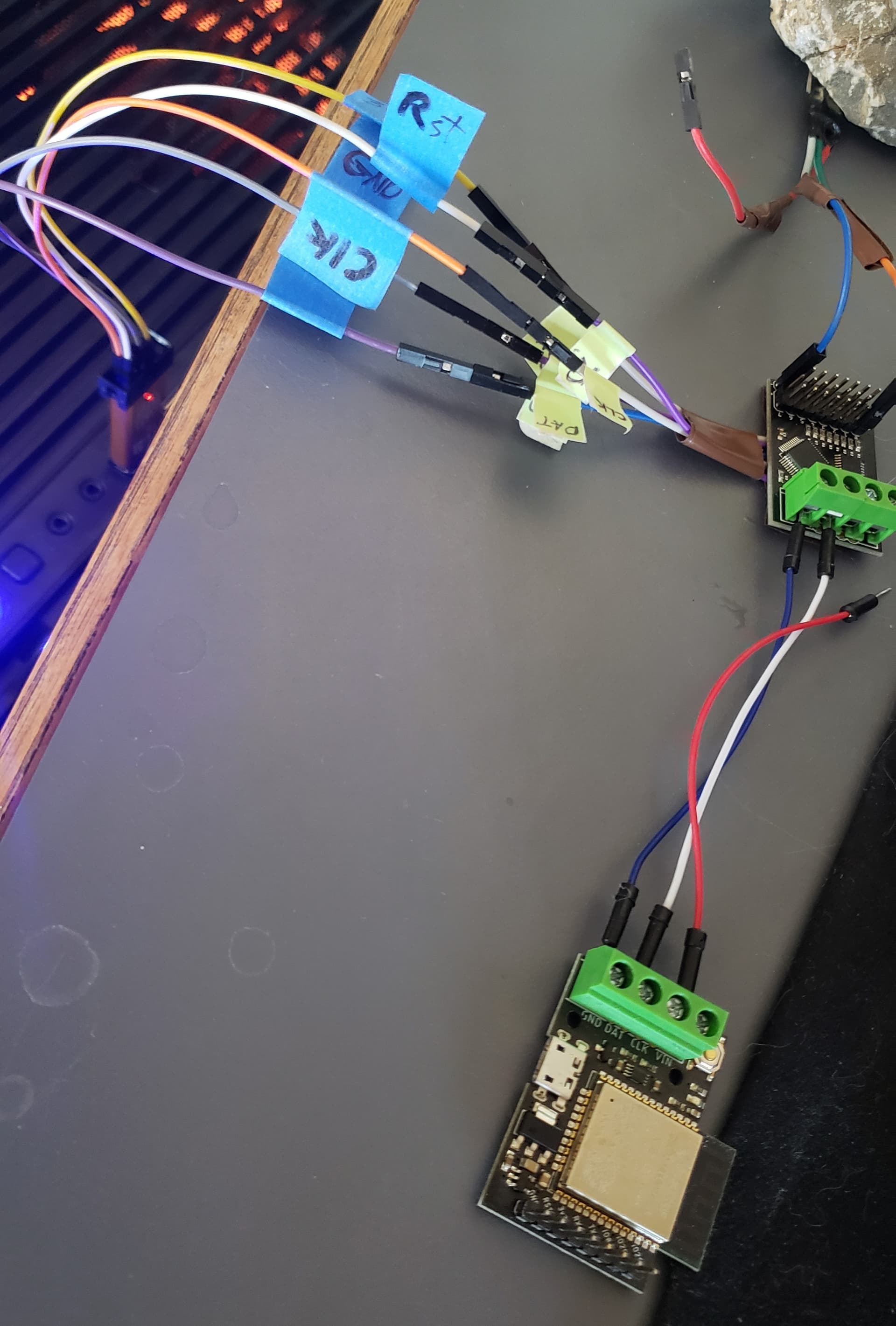
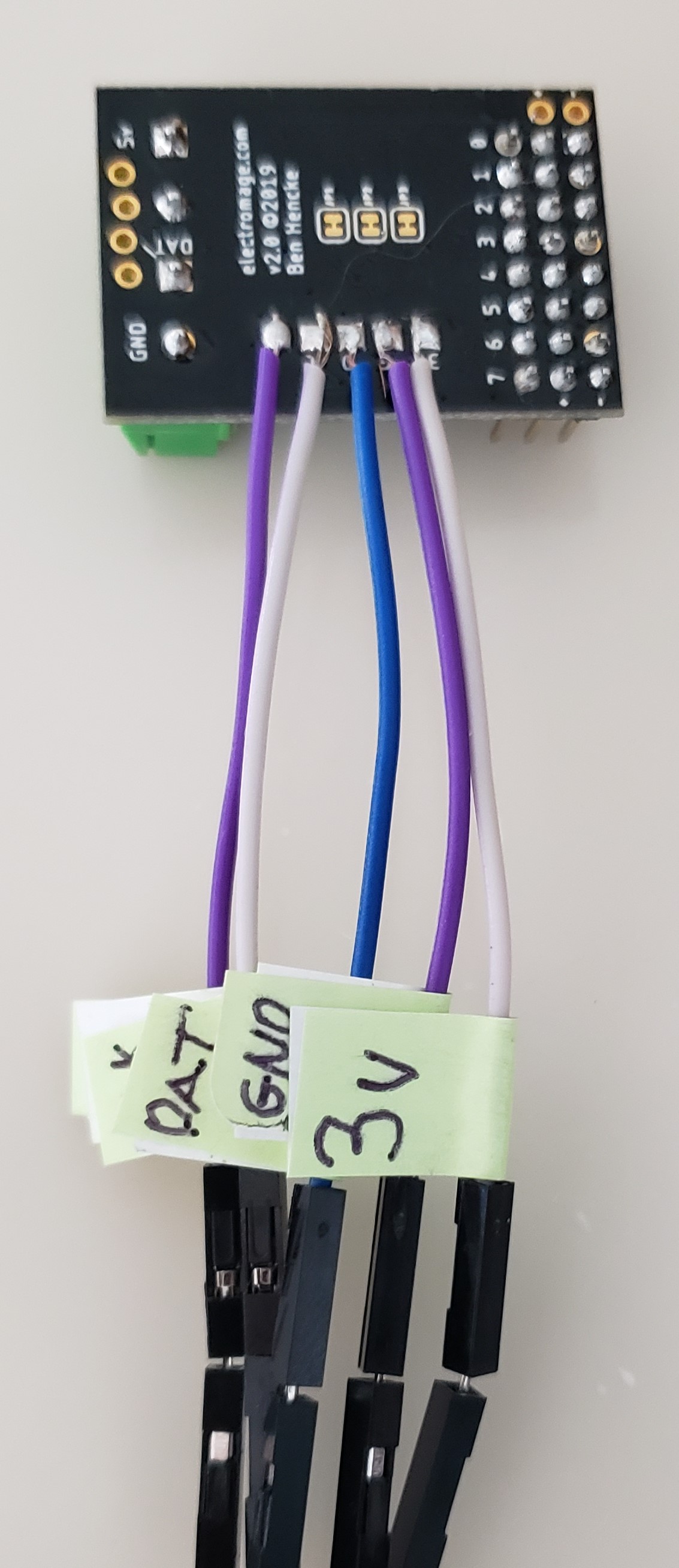
You’ll be connecting the 5 SWD(Serial Wire Debug)pads on the bottom of the output expander to the corresponding 5 line on your STM programmer. The required lines are 3.3v, GND, Data, Clock and Reset. If you’re going to do this frequently, you might want to order some pogo pins, and 3D print or otherwise craft a programming jig for yourself.

I just soldered short wires to the pads.

Programming the Output Expander

With your STM Programmer wired to the Output Expander and plugged into a USB port in your computer, open the STM32CubeProgrammer application. On the right hand side, you’ll see the ST-Link configuration window. Set the configuration as follows:

  • Port to SWD

  • Frequency to 4000

  • Mode to Under reset

  • Access port to 0

  • Reset Mode to Hardware reset

  • Speed to Reliable

  • Shared to Enabled

  • Uncheck Debug in Low Power Mode

  • Now click the “Refresh” icon next to the Serial Number field. Your Programmer’s serial number should be displayed.

  • Click the “Connect” button. If all is working properly, you should see a bunch of information about the Output Expander’s CPU. Now you’re ready to download the new firmware.

On the left hand side of the application, you’ll see a column of icons for selecting tabs. Choose the “Erasing and Programming” tab (second from the top, not counting the hamburger menu).

Use the file path control to select your .elf file. Depending on which build configuration you’ve chosen it will be “pixelblaze_output_expander.elf” in either the Debug or Release subdirectory.

Once you’ve chosen the file, press the “Start Programming” button. A few seconds later, your new firmware will be successfully installed on your Output Expander.

6 Likes

Thanks for posting this! I’ve got a yurt light dome project I’ve been working on using the WS2814 LEDS, which have an incompatible color order. The Wizard is working on adding support for that directly to the main PB branch, but in the meantime I’ve been having to do one of several hacks to be able to use the LEDS. I’m finally far enough along in the project that I want to start using the 3D mapping functions, so it’s chafing more that I don’t have direct support. Thanks to your guide, I’ve got the hacked code with the fix compiled, and the only reason it isn’t running right now is that the company you referred to on the link for the Emulator sent me the wrong device the first time. The replacement, which hopefully will be right, should be here on Saturday. I’ll keep you posted on whether it works.

3 Likes

I had a fun playing with the expander firmware, and am happy to know was it helpful to you! I look forward to hearing how your project goes!

I was tearing my hair out because I couldn’t get STM32 Programmer to get past a “No STM32 detected” error. I retested and resoldered all of the hardware, etc. But the problem was the Windows driver. After reading online that some dongles didn’t work with the newer software but still worked with the older ST-LINK software, I got that instead. Once installed it, both softwares now work. So you my have to get and install ST-LINK to get the programmer to work.

2 Likes

Good fix, and good to know! Looking back, I think I already had the old ST-LINK on my system from earlier work, so likely wouldn’t have even noticed the problem.

Before I flashed the OX board, the light would generally flash bright orange when it was connected to the ST programmer. Now that I’ve flashed the board, the light is a very dim, steady orange and the board doesn’t work anymore.

I’ve tried the following .elf files

  1. The expanderboard2.elf in the original firmware disti mentioned above
  2. A new .elf built from the original firmware disti mentioned above
  3. Built from @zranger1’s custom version

I’ve tried running the board both from the debugger connection and, after disconnecting that, from the PB. The behavior is the same for each one.

It’s worth noting that my expander board is a Version 3.0 from 2021. @wizard is it possible these .elf files aren’t compatible with the new version? If so can I at least get a compatible .elf file, if not an updated github project? I’m dead in the water here until I can figure this out.

Be sure to use the 3.x git branch!
There’s a bin and elf in the release director that should work.

1 Like

Doh! That was it, thanks!

Also, possibly the fastest reply time in hardware support history! Go @wizard!

Here’s the code I changed to get the Output Expander to work with the WS2814s. @wizard, this is a good reference for adding official support for them, as it’s tested and works. I made these changes in app.c. I’m only including the handleIncoming() function here. For the rest go to Github (see above)


static inline void handleIncomming() {
	uartResetCrc();
	//look for the 4 byte magic header sequence
	if (uartGetc() == 'U' && uartGetc() == 'P' && uartGetc() == 'X' && uartGetc() == 'L') {
		uint8_t channel = uartGetc();
		uint8_t recordType = uartGetc();
		lastDataMs = ms; //notice that we see some data
		switch (recordType) {
		case SET_CHANNEL_WS2812: {
			//read in the header
			PBWS2812Channel ch;
			uartRead(&ch, sizeof(PBWS2812Channel));

			if (ch.numElements < 3 || ch.numElements > 4)
				return;
			if (ch.pixels * ch.numElements > BYTES_PER_CHANNEL)
				return;

			//check that it's addressed to us and remap
			channel = remapFrameChannel(channel);

			// Original code
			// uint8_t or = ch.or;
			// uint8_t og = ch.og;
			// uint8_t ob = ch.ob;
			// uint8_t ow = ch.ow;
			/// Original code

			// Scott Mauer's hack for WS2814s
			// Set your PB and Output Expander for RGBW
			// This will re-arrange the colors to be correct
			uint8_t or = ch.og;
			uint8_t og = ch.ob;
			uint8_t ob = ch.ow;
			uint8_t ow = ch.or;

			uint8_t elements[4];

			uint32_t * dst = bitBuffer;
			int stride = 2*ch.numElements;
			for (int i = 0; i < ch.pixels; i++) {
				elements[or] = uartGetc();
				elements[og] = uartGetc();
				elements[ob] = uartGetc();
				if (ch.numElements == 4) {
					elements[ow] = uartGetc();
				}
				//this will ignore channel > 7
				bitConverter(dst, channel, elements, ch.numElements);
				dst += stride;
			}

			volatile uint32_t crcExpected = uartGetCrc();
			volatile uint32_t crcRead;
			uartRead((void *) &crcRead, sizeof(crcRead));

			if (channel < 8) { //check that it was addressed to us (not 0xff)
				int blocksToZero;
				if (crcExpected == crcRead) {
					if (channels[channel].type == SET_CHANNEL_WS2812
							&& (ch.pixels * ch.numElements >=
									channels[channel].ws2812Channel.pixels * channels[channel].ws2812Channel.numElements)
						) {
						blocksToZero = 0;
					} else {
						//we need to zero out previous data if the data received was less than last time
						blocksToZero = BYTES_PER_CHANNEL - ch.numElements * ch.pixels;
					}

					channels[channel].type = SET_CHANNEL_WS2812;
					channels[channel].ws2812Channel = ch;

					lastValidChannelMs = ms;
				} else {
					//garbage data, disable the channel, zero everything.
					//its better to let the LEDs keep the previous values than draw garbage.
					debugStats.crcErrors++;
					channels[channel].type = SET_CHANNEL_WS2812;
					memset(&channels[channel].ws2812Channel, 0, sizeof(channels[0].ws2812Channel));
					blocksToZero = BYTES_PER_CHANNEL;
				}
				//zero out any remaining data in the buffer for this channel
				if (blocksToZero > 0)
					bitSetZeros(bitBuffer + (BYTES_PER_CHANNEL - blocksToZero)*2, channel, blocksToZero);
			}
			break;
		}
		case DRAW_ALL: {
			uint32_t crcExpected = uartGetCrc();
			uint32_t crcRead;
			uartRead(&crcRead, sizeof(crcRead));
			if (crcExpected == crcRead) {
				startDrawingChannles();
			} else {
				debugStats.crcErrors++;
			}
			break;
		}
		case SET_CHANNEL_APA102_DATA: {
			//read in the header
			PBAPA102DataChannel ch;
			uartRead(&ch, sizeof(ch));
			if (ch.frequency == 0)
				return;
			//make sure we're not getting more data than we can handle
			if ((ch.pixels+2) * 4 > BYTES_PER_CHANNEL)
				return;

			//check that it's addressed to us and remap
			channel = remapFrameChannel(channel);

			uint8_t or = ch.or;
			uint8_t og = ch.og;
			uint8_t ob = ch.ob;

			uint8_t elements[4] = {0,0,0,0};
			uint32_t * dst = bitBuffer;

			//start frame
			bitConverter(dst, channel, elements, 4);
			dst += 8;

			for (int i = 0; i < ch.pixels; i++) {
				elements[or+1] = uartGetc();
				elements[og+1] = uartGetc();
				elements[ob+1] = uartGetc();
				elements[0] = uartGetc() | 0xe0;
				bitConverter(dst, channel, elements, 4);
				dst += 8;
			}

			//end frame
			elements[0] = 0xff;
			elements[1] = elements[2] = elements[3] = 0;
			bitConverter(dst, channel, elements, 4);

			volatile uint32_t crcExpected = uartGetCrc();
			volatile uint32_t crcRead;
			uartRead((void *) &crcRead, sizeof(crcRead));

			if (channel < 8) { //check that it was addressed to us (not 0xff)
				int blocksToZero;
				if (crcExpected == crcRead) {
					if (channels[channel].type == SET_CHANNEL_APA102_DATA
							&& (ch.pixels >= channels[channel].apa102DataChannel.pixels)
						) {
						blocksToZero = 0;
					} else {
						//we need to zero out previous data if the data received was less than last time
						blocksToZero = BYTES_PER_CHANNEL - ch.pixels * 4;
					}

					channels[channel].type = SET_CHANNEL_APA102_DATA;
					channels[channel].apa102DataChannel = ch;

					lastValidChannelMs = ms;
				} else {
					//garbage data, disable the channel, zero everything.
					//its better to let the LEDs keep the previous values than draw garbage.
					debugStats.crcErrors++;
					channels[channel].type = SET_CHANNEL_APA102_DATA;
					memset(&channels[channel].apa102DataChannel, 0, sizeof(channels[0].apa102DataChannel));
					blocksToZero = BYTES_PER_CHANNEL;
				}
				//zero out any remaining data in the buffer for this channel
				//TODO FIXME apa102 zeros will cause a start frame or maybe draw black? might not be what we want. set to all ones instead?
				if (blocksToZero > 0)
					bitSetZeros(bitBuffer + (BYTES_PER_CHANNEL - blocksToZero)*2, channel, blocksToZero);
			}
			break;
		}
		case SET_CHANNEL_APA102_CLOCK: {
			//read in the header
			PBAPA102ClockChannel ch;
			uartRead(&ch, sizeof(ch));
			if (ch.frequency == 0)
				return;

			//check that it's addressed to us and remap
			channel = remapFrameChannel(channel);

			volatile uint32_t crcExpected = uartGetCrc();
			volatile uint32_t crcRead;
			uartRead((void *) &crcRead, sizeof(crcRead));

			if (channel < 8) { //check that it was addressed to us (not 0xff)
				int blocksToZero;
				if (crcExpected == crcRead) {
					if (channels[channel].type == SET_CHANNEL_APA102_CLOCK) {
						blocksToZero = 0;
					} else {
						//we need to zero out previous data
						blocksToZero = BYTES_PER_CHANNEL;
					}

					channels[channel].type = SET_CHANNEL_APA102_CLOCK;
					channels[channel].apa102ClockChannel = ch;

					lastValidChannelMs = ms;
				} else {
					//garbage data, disable the channel, zero everything. Some apa102 channels could be without clock, so should remain unchanged
					debugStats.crcErrors++;
					channels[channel].type = SET_CHANNEL_APA102_CLOCK;
					memset(&channels[channel].apa102ClockChannel, 0, sizeof(channels[0].apa102ClockChannel));
					blocksToZero = BYTES_PER_CHANNEL;
				}
				//zero out any remaining data in the buffer for this channel
				if (blocksToZero > 0)
					bitSetZeros(bitBuffer + (BYTES_PER_CHANNEL - blocksToZero)*2, channel, blocksToZero);
			}
			break;
		}
		default:
			//unsupported frame type or garbage frame, just wait for the next one
			break;
		}

	} else {
		debugStats.frameMisses++;
	}
}

Another crazy wrinkle here is that, at least with OS X Catalina, if you download the Mac version of the ST tools from a Mac, IT WON’T RUN CORRECTLY. It has something to do with signing protection, etc. To get the Mac version to work, you have to DOWNLOAD IT ONTO A WINDOWS MACHINE FIRST, EVEN THOUGH IT’S FRACKING .ZIP FILE, unzip it, then copy it to your Mac. If you do that, it will install, and once you’ve done the Right-click-Open to give it permission to run an unsigned app, it will then continue working.

1 Like

The LEDS I’m dealing with are WS2814As, note the trailing A!
Imgur

I was playing around with my V2 expander(looking into changing the timings eventually), and managed to brick it. The onboard led doesn’t turn on and there is no output. I re-flashed the stock firmware(couldn’t find it pre-built, and could only build the debug version from the IDE for some reason, used that), re-flashed, same results. Any idea if I can try something else? Is there a prebuilt V2 firmware somewhere online? Did it on OSX then switched to Windows just in case.

There are prebuilt binaries here in the firmware/Debug directory of the 2.x branch on github. (And @wizard probably has better ones around somewhere!)

I don’t have any v2 expanders to test with though, so I’m afraid I’m not much help in that direction.

1 Like

That did it, I was using the wrong branch I guess. Thanks!

1 Like

Glad you got it back up and running! If you had been running and flashing it from a non-2.x branch then that would also explain why it wasn’t working when run from the IDE. The code between the 1.x, 2.x and 3.x are different enough that they are incompatible.

I had no idea we had so many expander firmware hackers! Awesome!

I’ve added a note / warning to the README for any future repo visitors

1 Like