Hi Electroimage Community.
I’m trying connect the Pixelblaze (which is working flawlessly with standard LED strips) to a NEON FLEX Strip I bought here.
Oddly enough, I was able to work with this product back in 2018, with OctoWS811 hardware and teensy 3.1
I have been impressed by the UX of pixelblaze, and wanteds to hook the two.
No luck for now!
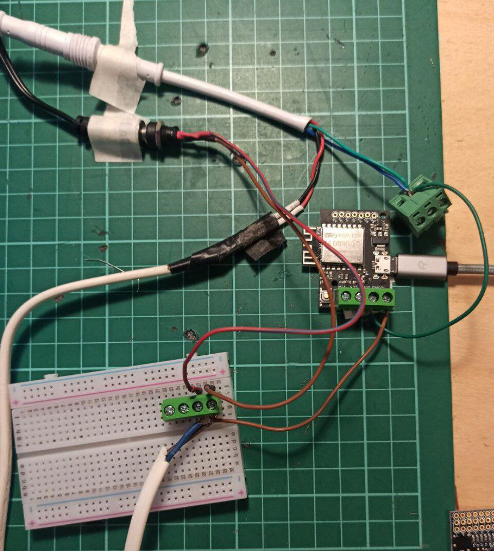
Wiring: I’m powering 12V into the strip. GND in common between LED strip and Pixelblaze. The other two wires were actually the same, to be hooked up to the DAT pin.
On paper the Pixelblaze should be compatible, but I’m running out of hope.
Any help appreciated. Here is the Datasheet for the LED-
ok.
I’ve put my hands on another flex neon strip. This one is 5m and I have no reason to doubt it used to be working.
I tested on the K-1000 with no luck👀.
I re-tested everything (all the connections) and retested with Pixelblaze, both WS2812 and WS2812 Buffered, at all speeds…
Here is my setup.
Any ideas?
I’m running Pizelblaze v2.15
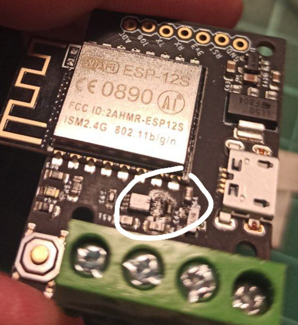
By disassbleing the setup and touching the board I noticed a part very hot, and I discovered I probably burned an IC.
Since I have never poweered the board with my 12V source, how do you think this is possible / have happened?
Well, at least you’re making progress and getting to the bottom of things.
I’m not sure the product you linked as “spec sheet” is this one… it clearly shows 3 wires and claims a WS2811 IC.
Just wanted to point out this thread as well; similar in that it’s a 12V, dual-path NeoPixel, but spec sheet says to ground the backup input. I see from your picture it looks like DAT is conected to two of the 4 wires going to your LEDs.
I have seen hybrid strips that combine addressable LEDs with an analog/PWM LED channel. These can be “common anode” which means the LEDs are powered, and the “input” just need to be grounded to turn on. The effect of that is that you might have 24v (minus some drop from the LEDs) on that blue wire.
If that is true, then it likely blew out the output driver on Pixelblaze and destroyed the digital input on the LEDs. Your strip looks like there are several LEDs per “pixel” and you can probably cut that segment out.
You might test your Pixelblaze with a known-supported LED strip to see if its still working.
I would power the strip separately and measure both of the input pins to the strip. If you detect a voltage (relative to GND), do not connect it to PB.
Set LED type to Buffered WS2812, leave data rate at default. Be sure to connect GND between both systems, and power PB with a separate 5v supply (like from USB as you have pictured above).
For now, I would leave them separate. If you run in to issues, try grounding the 2nd input.
 .
.