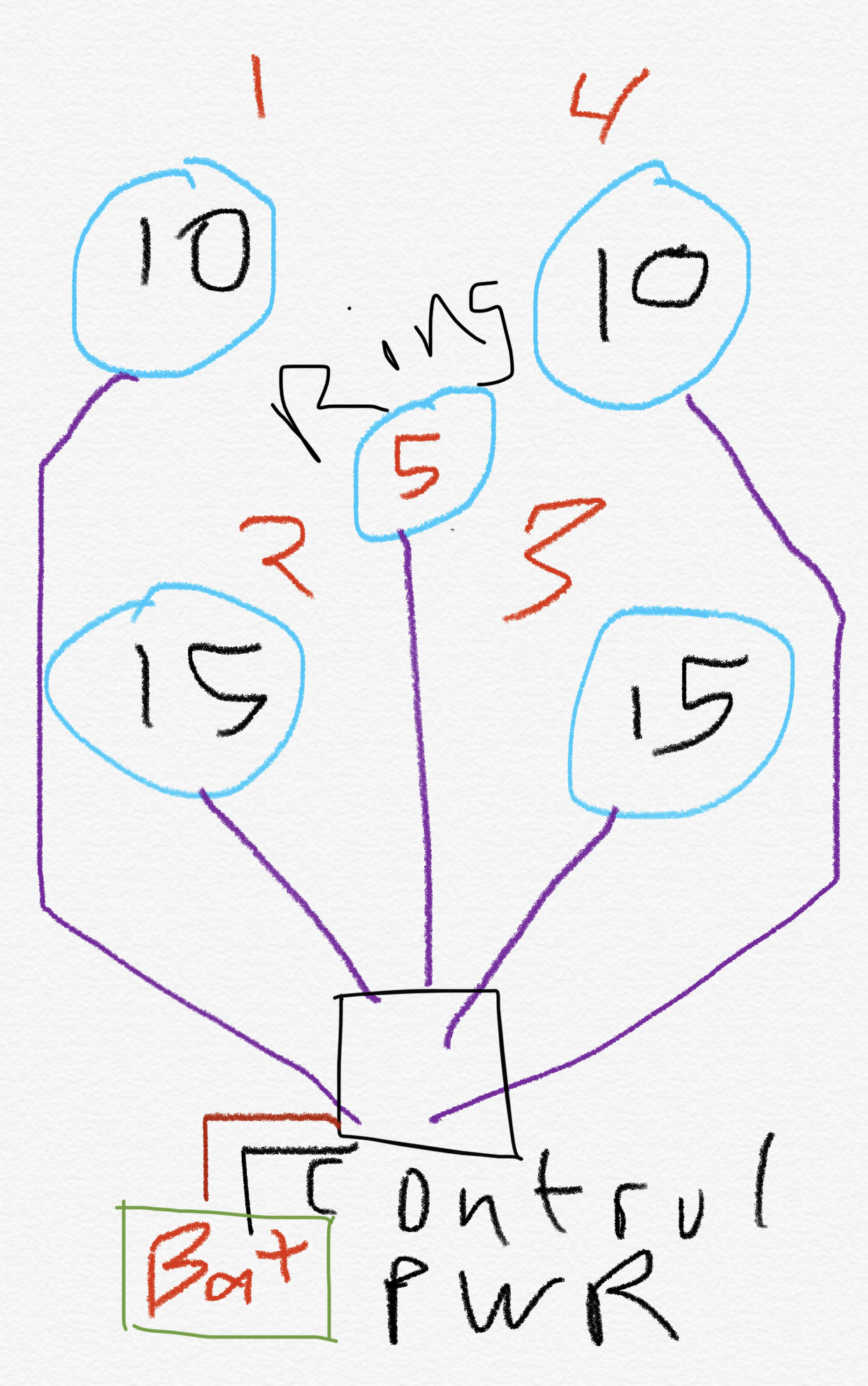
Looking to get some code for a project I am creating with 4 ws2811 strips of lights and a center of 9 rings in the middle of the 4strips. I would like to have a button to change the patterns and a knob to change the speed of the patterns if at all possible. Would be even better if I could have a button to tap for the frequency or bpm or speed of the patterns. Bonus if their could be a mic build into it for the lights to dance to the music. Possibly be able to edit the patterns by my phone or mobile browser would be awesome or load the program on a arduino or other device. I know this would be a lot to design but I would be willing to pay someone if they could help code/ design it with me.
What you’re going to need is a sensor expansion. It’s got your gpio’s, as well as a mic, audio jack, optical sensor, accelerometer, etc.
The buttons to switch modes might be tricky since all the inputs are analog (unless there’s a better way I don’t know about). You might need a bit of code that checks for the value to reach a threshold, throw a flag, and wait for it to drop below the threshold again.
Those analog ins are what you want to use for the knob(s).
Possibly be able to edit the patterns by my phone or mobile browser would be awesome
This functionality comes with a Pixelblaze. That’s the default way to work with it.
As far as the layout described in the drawing, the pixelblaze software comes with a 2/3 dimension mapper. That’s what you want to use to describe to the pixelblaze how your pixels are laid out.
This is perfect. Thank you. This might be a stupid question but is pixelblaze loaded already onto these boards on here or do I need to load anything to get started?
Pixelblaze is a board that comes preloaded with the firmware. It comes with an instructions sheet (Pixelblaze printout insert.pdf (206.6 KB)) that guides you through connecting to it over WiFi and then configuring it to connect to your WiFi network.
From there, it provides a web server on it’s IP address that serves an in-browser code editor (IDE). It includes example code pre-loaded to get you going, and you can upload any other examples you grab from the pattern library.
GP0 is a pin that’s already wired to the mini button on the board. If you long-hold it performs a WiFi reset, but short presses will simply advance the current running pattern to the next one. Therefore, if all you need is a button to go to the next pattern, I might use the one preinstalled on the v2+ board or connect a more accessible button to that same GP0 (also exposed via pin 6 on the expansion header) with some wire.
@cjn566 You might be right for the ADC pins on the sensor expansion board, and he’ll definitely need the expansion board to get the sound data.
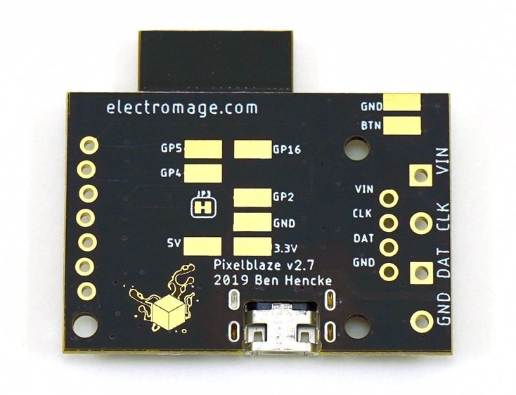
You can do digitalRead() on the GPIO pins on PixelBlaze itself. GPIO 4 and 5 are exposed on the underside solder pads:
GP4 and GP5 are the most straightforward to use; GP2 and GP16 have special cases that are documented.
// This example code is for Pixelblaze v2+
pinMode(5, INPUT_PULLUP) // GP5 solder pad on the underside

export var w1 = -1 // Enable the variable watcher in the IDE
export function beforeRender(delta) {
  w1 = digitalRead(5) // w1 will be 1 when NC (not connected), 0 when grounded
}