I’m building a burner bike and I’m running into issues with the SK9822 (APA102) LED strip that refuses to respond properly to data/clock signals. The strip lights up, but doesn’t show the correct patterns from the V3 Pixelblaze. I suspect there’s a physical connectivity issue somewhere on the strip, but I’m struggling to identify exactly where. Or maybe I’m missing something here.
What I’ve Tried:
I forgot to test the strip before I installed it. Lesson learned there. I zip tied it to the back half of the bike already.
Power/Ground Continuity: My multimeter shows good continuity on 5 V and GND across the strip and power delivery looks good.
Visual Inspection: Didn’t see obvious cracks or severe bends in the strip, but it’s hard to be certain. The strip is IP67, making it hard to interact with the strip.
Tried with and without the connector that switches the data/clock wires.
Cut Off First Pixel: I removed the very first LED and re-soldered the input, but the strip still has the signal issues. I thought maybe it was some solder issue but no sign of a fix.
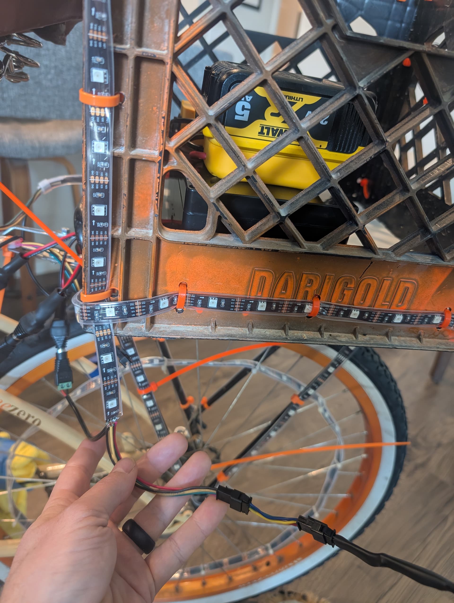
Arrow is pointing away from PB so it is the first pixel.
Symptoms:
Random lighting/colors but some similarity to the cadence of the pattern set in PB.
Setting fewer LEDs than the 150 in the strip does reduce the number that light up but not by the correct amount. Change pixel number in software to 10 but more like 12 pixels light up.
Another identical strip on the same setup works perfectly, so the controller and wiring (power, GND, clock, data) should be okay.
I am leaning toward some hardware issue with the strip. Any other ideas?
How can I pinpoint where the break or connectivity fault is within the strip?
Are there typical places these strips fail (solder joints between segments, or near the first LED)?
Any tips on systematically narrowing down the fault would be super helpful.
Thanks in advance for any guidance! I appreciate any best practices or experiences with SK9822 strip troubleshooting.
Some clear pictures of your setup showing all wiring and connections, or a sketch of your physical wiring layout, goes a long way toward getting help with troubleshooting these types of issues.
My first questions would be: what is your power source, and what is the length of the wires connecting the PB to your malfunctioning LED strip?
(2) DeWalt 20 V (5 Ah) Battery → (2) Low-Voltage Cutoffs (LVC)
a. I use a small LVC module set around 15.5 V so the battery never goes below a safe level for its 5‑cell Li-ion pack.
LVC → Buck Converter (5 V Output)
a. The LVC feeds the buck converter (rated 20 A), which steps down from ~18–21 V to a stable 5 V.
Buck Converter (5 V / GND) → Start and end of both LED Strips
(2) SK9822 5m strips both share this 5 V and a common ground at the start and end of strip
One of the strips works great. Then I take the same power output plugs and unplug the first strip and then plug in only the second strip, I have the issues. The connections are all 6-12 inches long with the power unit in the rear bike basket and both strips start and end at the same location next to the power source. I don’t think power delivery is the issue.
I tried the quick connection that came with the strip that flips the clock and data lines. Both with and without it that I have similar issues. They light up but nothing like the pattern selected. I also have two V3 Picos that I am using for separate wheel systems and those seem to have the same issues where it works great on one strip but weird non-sense patterns on the other strip. Tried the Pico both with and without the clock and data swap with no progress.
I got frustrated before I posted and just chopped the first pixel and soldered new connections thinking that maybe it was some clock/data solder issue from the factory but then the same issue was there.
How is the malfunctioning LED strip attached to your bike? If you used the adhesive backing to mount it to something metal, sometimes the copper traces on the bottom of the strip can short out in places where the thin adhesive coating gets breached. See if you have any unwanted continuity from any of the strip connections to your basket or bike frame.
Good idea but it has the IP67 plastic wrap fully around the strip and it is zip tied to the basket. There are some twists and bends of the strip but no cuts to the wrap. I tried to limit the bends but my only thought is that one of them crossed the data and clock signals somewhere. I still can use the PB to limit the Pixel count of the strip. Although the number of pixels (N) I enter into the setting is then lighting up N +3ish pixels. Not sure if there are good ways in the software to help determine if/where there is a hardware issue?
I’ve not used this type of strips, but are you sure that you are using clocked strips here? The inner 2 lines appear to be labelled D1 and D2, which might mean you have a data line and a backup data line.
Yeah, the examples I find on a quick google search shows clocked strips have C and D lines, not D1 and D2. Try setting the pixelblaze to a different strip type and disconnect the clock line.
From the pic, that doesn’t look like an SK9822 strip. I see resistors located between each and every pixel on the strip in the pic. I use SK9822 strips and there are a few resistors here and there, but not between each pixel.
This is why I needed another set of eyes here. I ordered three rolls of Sk9822 and two were that but there was a third that was a GS8208 12v strip. That is why I am having so many issues. So clearly this won’t work for for this setup. Wrong strip didn’t even cross my mind
Thanks for all the help! I’ll be sure to post the finished product when I get there.