The orange light is on at a dull level. I have tinkered with the settings a lot, and am currently at 144 pixels (I counted) 2 MHz, GRB (?). I have used a multimeter to check that I can get for power and ground I can get from the chip to the strip. Harder to check Clock and Data, but I do seem to get from the LED connector to the board.
I haven’t done a lot of this kind of wiring work in a long time, so even simple suggestions might help. What am I doing wrong??
So if I understand it, you are reading 5V with a voltmeter on the actual strip’s copper pads, correct?
Sometimes when this has happened to me, I found I had simply miswired the four lines. Different strips will commonly switch the clock and data line in an order that does not match Pixelblaze’s. It’s good to use the continuity function on your multimeter to verify all 4, reading the tiny markings on the strip.
Another common mistake is that I accidentally connect Pixelblaze to the Data Out side instead of the Data In side of the strip.
And yet another common thing we’ve heard is people had a bad solder joint on the Pixelblaze board where the screw terminal block was soldered on. We won’t solder shame you if you want to post a picture!
How are you powering everything? 144 LEDs (8.6A max) is too much for the micro USB connector on the board (1.8A max) unless global brightness is set to something like 10%. But if that were your problem you might have seen something first.
Another thing you can test: if you disconnect the clock and data but keep the strip powered, if you brush your fingertips across the data and clock contacts, you can sometimes “send noise” and it will light up some of the pixels randomly. This at least verifies that power is correct and that the first pixels in the chain are passing data along, so it’s back to check the connections closer to the board.
@jeff made some great points to check… I’ll add one more… did you set the correct pixel type? That one tripped me up with the Pico the first time. (I later had problems with not enough voltage when the pixels were all lit, so keep an eye on that voltage at the Pico end!
Best regards.
Thanks all! Turns out it was two rookie mistakes. I was using the USB power, so I swapped to 5V (once I got one) and then somehow the 5V terminal was cold, so I had to rescrew it. But now it works! Joy!
Do you folks have good ideas for portable 5V power? I’d like to put this in a costume. I can also start a separate thread…
If you have modest power requirements, those USB phone charger battery packs make very handy portable power supplies for Pixelblaze and LEDs. I usually reach for those for costumes given the universality and ease of swapping them out when one is depleted. On larger setups I’ve used a pair.
In practice you can run with a lot more than 10% max brightness and oversubscribe your power budget as long as your patterns are displaying color and/or with varying brightness as part of the pattern (pretty much any of the included patterns would qualify). The SK9822’s have amazing performance at lower levels too. The 8.6A figure is a valid worst-case scenario, but unless you really need to be a giant flashlight and display 100% white you can go quite far with a 1.8A budget on 144 LEDs.
Every USB battery pack I’ve used will cut power if you draw too much, which is easy to test/verify for your own safety, and gives you some confidence that your worst case scenario is everything losing power. I did have one brand of pack that needed to be “reset” by connecting it to power briefly as if it was being charged, but most of them recover on their own.
For costumes I’ve also found it handy to connect up a potentiometer to an analog input and use that to modulate brightness in pattern code. This lets you have a physical control for adjusting brightness as you go from dark to well-lit areas, and gives you a way to recover if a pattern does use too much current and causes a temporary power reset. I have a coat that hides a sensor board with a few buttons and a pot in the sleeve.
Ah, thanks! Indeed, it was not the 5V power, just the loose connection. On the other hand, I had lost the charger for my portable USB charger, which happens to be… a the 5V charger I just bought, so it all works works out in the end.
Cool tip on the pot – I’ll look into that. How does the sensor board work?
To reiterate what Ben is saying. I used a small rechargeable USB battery pack to power 6 feet of 60Lpm ws2812 for my Halloween costume they stayed lit fot about 4 hours!
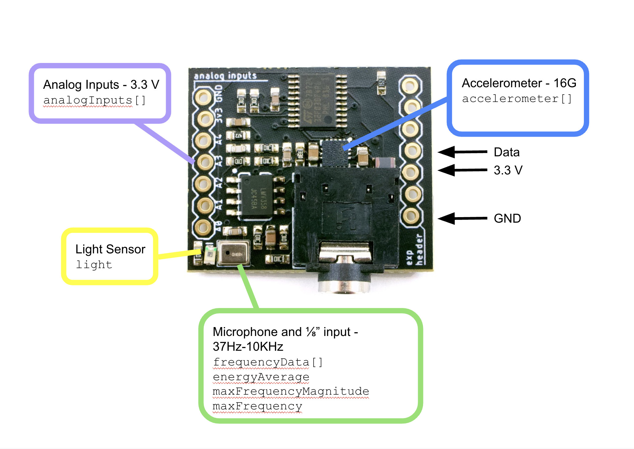
It can be connected directly to PB mounted or remote with 3 wires. You can get a single pot and some buttons using the built-in GPIO on the V3 without the sensor board, but will be more wires back to the PB. All of the data from the sensor board shows up as variables in PB that are automatically updated.
For my coat I also wanted to have sound reactivity anyway, and thought having the accelerometer on my arm movements could be used for some neat effects. I could use some of the analog inputs as buttons by adding an external pull up resistor, giving an analog value that was either close to 0, or close to 1. Overall it worked out pretty well with all the inputs fed back to PB with only 3 wires.
On the LED side of things, I used a pair of output expanders, with one USB pack powering the PB + one expander, and the other pack powering the second expander. From each expander I ran a number of LED strips.