Mapping 6 rings at various angles/positions

I am working on a sculpture which will be fully internally lit, using 1,200 LEDs across 6 strands. Each stand forms a ring, and the rings are arranged into this shape:

How would I map 6 rings, where I could specify the unique positioning of each one?

The current plan is to map it in TouchDesigner and export a JSON file with x,y,z coordinates for each LED. But I keep thinking that if my math/programming was better it would be possible to do it more elegantly as a set of ring formulas.

I read Hexadecachoron - Polytope Wiki but youā€™re going to have to tell us what 3D projection you are using.

Just to get you a feel for the code: Suppose the strands are all wired in order (or on an output expander) and you just want stacked rings, just off the top of my head:

function (pixelCount) {
  strands = 6
  leds_per_strand = 200
  for (strand = 0; strand < strands; strand++) {
    z = strand / (strands-1)
    for (led = 0; led < leds_per_strand; led++) {
      angle = (led / leds_per_strand) * (Math.PI * 2)
      x = cos(angle)
      y = sin(angle)
      map.push([x, y, z])
    }
  }
  return map
}

Iā€™m thinking youā€™re trying to build the shape on the Kickstarter page thatā€™s labeled ā€œHenry Segermanā€™s Visualizing Mathematicsā€¦ā€ correct? That looks to me like six rings that can be defined by the fact that any ring touches 2 points of an inner tetrahedron, and 2 points of an outer one, right?

http://www.3dprintmath.com/figures/3-18

My guess is that any ring in 3D space can be defined by 3 points, and that its angle in space means that each of its x, y, z locations is going to be a sinusoid with phase offset, just like Sorcererā€™s example is x and y with a 90 degree phase offset (sin vs cos). Itā€™s probably take me a couple hours I donā€™t have right now to make a working map generator, but I hope this, along with sorcererā€™s answer, gets you closer.

1 Like

Correct Jeff, thatā€™s exactly what Iā€™m hoping to create. It does get me closer, although Iā€™m still going to struggle with the code/math to make this a reality

Thanks for finding those different views, Jeff, and especially for pointing out the bit about the tetrahedrons.

It seems to me that the centres of the circles are going to be at the points of an octahedron, and to keep those straight, I would think of the shape as depicted in the bottom right image on 3dprintmath, rotated 45Ā°. Then the front and rear rings are at 45Ā° (90Ā° to each other) about the depth axis and ā€¦ well the other pairs are like that too!

After this little bit of thinking, itā€™s not gonna take a couple of hours to implement. Coming right up.

This will be a programming challenge, and Iā€™ll need help, which means I canā€™t promise itā€™s possible to get the lights to do exactly what I want, but the lights will do something more interesting than just blinking red to green to blue.

I think youā€™re going to knock this part out of the park! :relaxed:

See? Implementation took 15 minutes once the process was clear! Iā€™m assuming that the beginning and end of each ring are at the centre of the piece.

function (pixelCount) {
  radius = Math.sqrt(2)
  map = []
  strands = [
    [-1, 0, 0, 0, 1, 1 ],
    [ 1, 0, 0, 0,-1, 1 ],
    [ 0,-1, 0, 1, 0, 1 ],
    [ 0, 1, 0,-1, 0, 1 ],
    [ 0, 0,-1, 1, 1, 0 ],
    [ 0, 0, 1,-1, 1, 0 ],
  ]
  leds_per_strand = 200

  strands.forEach(strand => {
    cx = strand[0]
    cy = strand[1]
    cz = strand[2]
    ux = strand[3]
    uy = strand[4]
    uz = strand[5]

    for (led = 0; led < leds_per_strand; led++) {
      angle = (led / leds_per_strand) * (Math.PI * 2)
      x = Math.cos(angle) * radius
      y = Math.sin(angle) * radius
      map.push([
        cx - x * cx + y * ux,
        cy - x * cy + y * uy,
        cz - x * cz + y * uz,
      ])
    }
  })
  return map
}
3 Likes

:exploding_head:

Hahaha OMG maybe for youā€¦ some of yā€™all see what Iā€™ve made and assume Iā€™m really good at this, but you have no idea how many hours I allocate :slight_smile: That transform matrix is really cool. Is there a particular online resource you used for it or did you work it out yourself?

2 Likes

Worked it out myself. Easy-peasy! :stuck_out_tongue: Let me walk you through it:

Each strand is [cx, cy, cz, ux, uy, uz] ā€¦ the ā€˜cā€™ vector is the centre of the ring, the 6 points of an axis-aligned octahedron. I figured this out from your tetrahedron tip and swinging the 3D model around and imagining the positions of those points. I realized they were at the faces of a cube which are of course the points of its dual, the octahedron. In retrospect this should have been obvious since there were 6 of them and the shape is symmetrical.

For each circle, we need two vectors to add to the centre, one for the x (cosine) and y (sine) distance. The centre of each circle is already a vector from the origin, so we can just re-use that and subtract it times the cosine from the centre so that the x component of the ring starts at 0 (because cos(0)=1). Then we need this ā€˜uā€™ vector which is at right angles to the ā€˜cā€™ vector, and rotated 45Ā°, so I put something in the elements not used in ā€˜cā€™. Since sin(0)=0, this component also starts at 0. Come to think of it, these should not be Ā±1, they should be Ā±sqrt(2) to be the same length as ā€˜cā€™. ā† NB correction needed!

Then I added this ā€˜radiusā€™ variable to change the size of the circles. An alternative would have been to multiply the first ā€˜cā€™ vector the map.push but in the end it amounts to the same. sqrt(2) seemed like a plausible value which made the mapper preview look a lot like the 3dprintmath images. Maybe that should just be on a slider!

2 Likes

@sorceror, I worked this out from the same starting point ā€“ the faces of a cube ā€“ but using a clunkier, ā€œbuild complete ring centered at origin, then transpose and rotate. Rinse, repeat x 6ā€ method. Your approach is awesomely more elegant!

Big shout out to @jeff for admitting that all this ā€œeffortlessā€ math stuff we do sometimes takes work! Definitely the case for me.

Hereā€™s a short test pattern that I used to see what was going on while I was grinding away. It shows the rings in different colors, has a white bar that traverses the whole assembly in order, etc.: (tiny video below)

var pixPerRing = pixelCount / 6;
var halfRing = pixPerRing / 2;
var c;
export function beforeRender(delta) {
 c = floor(pixelCount * time(0.061));

}

export function render(index) {
  f = index/pixPerRing;
  h = .618 * floor(f);
  s = abs((index - c)) > 10;
  v = 1-abs(halfRing-(index % pixPerRing))/halfRing;
  hsv(h, s, v*v)
}
2 Likes

Wow, Iā€™m thrilled yaā€™ll. The test patterns look amazing. I almost have the 3d structure setup full-size, and Iā€™ll post videos here when itā€™s running!

2 Likes

Some success, and some challenges! My wiring/hardware setup is evolving, so I was only able to connect 3 rings tonight. Still, I uploaded the mapper code and tested out a few patterns, including the test pattern from @zranger1 . It might be too early to really troubleshoot this, but i wanted to share my excitement.

zranger1 test pattern:

cube fire 3d:

Because this will be wired from the junctions, the exceptional version of this project will be able to note where on the structure each string starts from ā€“ three of them will start from the junction listed here, and the other 3 circles will start from the three remaining inner junctions. Being able to wire it up such that it matches the mapper is in itself no easy task!

3 Likes

@mogmaar, your project is going to look fantastic!!

Iā€™d just wire the rings in the way that makes it easiest to build. Itā€™s conceptually pretty easy to change where a ring starts in the mapper ā€“ you just change the rotation of the LED coordinates for the ring.
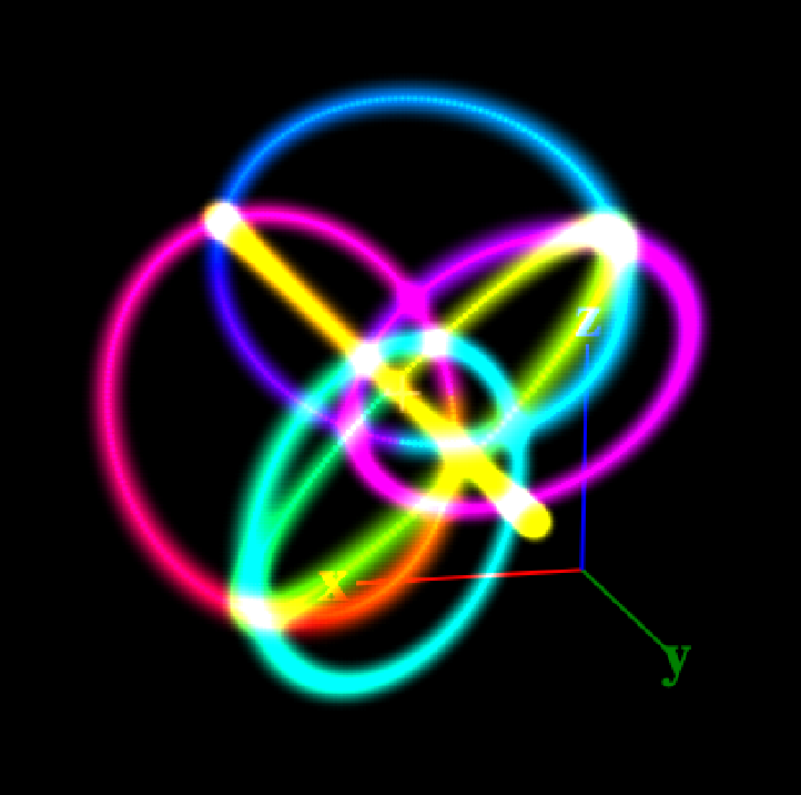
Hereā€™s a version of the mapper that lets you shift the origin of each ring by an arbitrary number of pixels. Just enter the value you need, positive or negative, for each ring into the origin_shift array.

It is set up to shift ring 0 by 30 pixels. Iā€™ve included a very short pattern at the bottom of this message to show where the rings start ā€“ make your changes to the mapper, then switch to the editor window to see how it looks.

To get rid of the shift for a ring, just set the ringā€™s origin_shift value back to 0. (and please forgive my slightly clunky mods to @sorcererā€™s very elegant javascript.)

function (pixelCount) {
  radius = Math.sqrt(2)
  map = []
  strands = [
    [-1, 0, 0, 0, 1, 1 ],
    [ 1, 0, 0, 0,-1, 1 ],
    [ 0,-1, 0, 1, 0, 1 ],
    [ 0, 1, 0,-1, 0, 1 ],
    [ 0, 0,-1, 1, 1, 0 ],
    [ 0, 0, 1,-1, 1, 0 ],
  ]
  leds_per_strand = 200
  
  // number of pixels to shift the origin of each ring
  // can be positive or negative.
  origin_shift = [30,0,0,0,0,0]
  
  strands.forEach((strand,index) => {
    cx = strand[0]
    cy = strand[1]
    cz = strand[2]
    ux = strand[3]
    uy = strand[4]
    uz = strand[5]

    // shift the origin the ring by some number of pixels
    // number of pixels
    theta = (origin_shift[index] / leds_per_strand) * (Math.PI * 2)     
    
    for (led = 0; led < leds_per_strand; led++) {
      angle = theta+(led / leds_per_strand) * (Math.PI * 2)
      x = Math.cos(angle) * radius
      y = Math.sin(angle) * radius
      map.push([
        cx - x * cx + y * ux,
        cy - x * cy + y * uy,
        cz - x * cz + y * uz,
      ])
    }
  })
  return map
}

Short pattern to show you where each ring starts:

var pixPerRing = pixelCount / 6;
var halfRing = pixPerRing / 2;
export function beforeRender(delta) {
}

export function render(index) {
  h = .618 * floor(index/pixPerRing);
  v = 1-abs(halfRing-(index % pixPerRing))/halfRing;
  hsv(h, 1, v < 0.02)
}
3 Likes

huge progress here! Iā€™ve been talking up how grateful I am for the genius of the people on this forum!

First, the success ā€“ today I finally assembled the full project with the LEDs inside. We are using the mapper code exactly as you all created it here.

We wrote this simple program to calibrate the offset, and re-arrange some of the rings to match what exists in physical reality. By running this for z, and then for x, and then for y, it works well. Because this will be disassembled and then re-assembled, there will be calibration every time we wet it up, and this code seems to make it easy:

export function render3D(index, x, y, z) {
  top = time(0.1)
  bottom = top - 0.05
  hsv(.5, .5, z < top && z > bottom)
}

Z axis works! Z axis HexadechacorOn - YouTube
X axis works! X axis HexadechacorOn - YouTube

The problem weā€™re running into is that we think one of the rings is essentially running backward. We would like to know how to map the ring in reverse essentially. Either that, or flip it on itā€™s own axis? Hereā€™s a video of the Y access, and youā€™ll note the far left ring is essentially starting in the middle instead of the edge like youā€™d expect.

Y axis - small problem: Y axis HexadechacorOn - YouTube

We tried flipping all the variables in the mapper and basically banged our heads against this for a few hours. Help?

To flip it along the Y axis, try adding another variable like origin_shift as in zranger1ā€™s code but call it ā€¦ y_flip = [1,1,1,1,-1,1] where the -1 is in the position of the flipped ring. Then use y = Math.sin(angle) * radius * y_flip[index] to calculate Y, and youā€™ll be flipping Y (relative to its center) for only the ring marked with -1 in y_flip.

thank you! thatā€™s super helpful - I added a slider for more straightforward calibration and added the y_flip (and an x_flip) as you suggested. Itā€™s super close, but still getting stuck. I canā€™t get ring 5 to flip so it works with all 3 axes - it seems to only be right for the z axis or tye y axis but not both.

And map, for reference:


function (pixelCount) {
  radius = Math.sqrt(2)
  map = []
  strands = [
    [-1, 0, 0, 0, 1, 1 ], // 0
    [ 0, 1, 0,-1, 0, 1 ], // 3
    [ 0, 0, 1, -1, 1, 0], // 5
    [ 0, 0,-1, 1, 1, 0 ], // 4
    [ 0, -1, 0, 1, 0, 1 ], // 2
    [ 1, 0, 0, 0,-1, -1 ], // 1
  ]
  leds_per_strand = 200
  
  // number of pixels to shift the origin of each ring
  // can be positive or negative.
  origin_shift = [-15,85,-15,15,15, 15]
  
  // flips each circle to rotate clockwise or counterclockwise 
  // across the corresponding axis
  y_flip = [1,-1,1,1,-1,1]
  x_flip = [1,-1,1,1,1,1]

  strands.forEach((strand,index) => {
    cx = strand[0]
    cy = strand[1]
    cz = strand[2]
    ux = strand[3]
    uy = strand[4]
    uz = strand[5]

    // shift the origin the ring by some number of pixels
    // number of pixels
    theta = (origin_shift[index] / leds_per_strand) * (Math.PI * 2)     
    
    
    for (led = 0; led < leds_per_strand; led++) {
      angle = theta+(led / leds_per_strand) * (Math.PI * 2)
      y = Math.sin(angle) * radius * y_flip[index]
      x = Math.cos(angle) * radius * x_flip[index]
      map.push([
        cx - x * cx + y * ux,
        cy - x * cy + y * uy,
        cz - x * cz + y * uz,
      ])
    }
  })
  return map
}

Oh great! A game of mathematical whac-a-mole!

How about reversing the _flip in the Z calculation? (cz - x * x_flip[index] * cz + y * y_flip[index] * uz)

Or maybe add a z_flip[] and use it instead of the other _flips there? I know an old lady who swallowed a fly ā€¦ :smiley:

2 Likes

That did it! Not quite like you suggested, but I added a z_flip parameter and put it in the z calculation with the line (cz - x * x_flip[index] * cz + y * z_flip[index] * uz),

Hereā€™s a preview of ā€˜sorcery 3dā€™ working perfectly. Will share more when itā€™s dark out. X y and z all aligned!! - YouTube

@sorceror - youā€™re a hero. Whereā€™s your tip jar or similar way I can show my appreciation?

1 Like

Iā€™m a Burner! Itā€™s a gift. Keep gifting and burn brightly! :heart:

1 Like