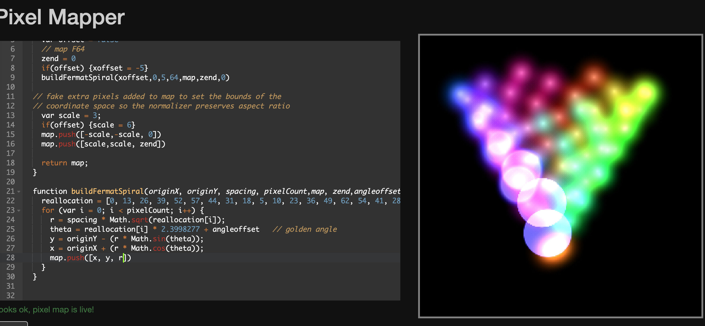
Mapping Complex Objects

OH, you’re right, the LED order isn’t the spiral order. Fixable though… since Jason has provided a translation table.

I’ll post code to help with that in a sec. Ok, I added it above.

basically this:
0, 13, 26, 39, 52, 57, 44, 31, 18, 5, 10, 23, 36, 49, 62, 54, 41, 28, 15, 2, 7, 20, 33, 46, 59, 51, 38, 25, 12, 4, 17, 30, 43, 56, 61, 48, 35, 22, 9, 1, 14, 27, 40, 53, 58, 45, 32, 19, 6, 11, 24, 37, 50, 63, 55, 42, 29, 16, 3, 8, 21, 34, 47, 60
is the ‘real location’ of the indexed pixel… so led 1 is spiral 13, 2 is 26, etc.
Since we can use real JS in the mapping, it’s as easy as pasting that as array, and using the i as the index to it.

Also, if you use r (radius) to modify zend, you’ll get the cone we talked about with the center at the top
here’s just r in place of zend… That’ll make your Z rings really easy…

2 Likes

sidebar, why can we initialize arrays in the mapping but not in patterns?
Cause that would be :: chefs kiss ::

Because the mapping is in the browser, and it’s real javascript. The patterns aren’t real javascript, but the PB subset/flavor that @wizard has written support for.

But I agree, the ability to do X = array[1,2,3,4,5…] would be awesome.
I’ve been porting lots of JS code, and I have a dozen workarounds in my head or more because code as written doesn’t work on PB.

BTW, I re-looked at the first photo, and absolutely, if you use radius for your Z, you’ll be most happy. If Z runs from the center of the disc, and gets bigger in circles (aka radius), it’ll make circles on the disc, then it’ll light up the rings, then it’ll get smaller on the other disc… So just a simple Z-axis line will run along the entire mask, lighting it up like a tube from one end to the other. Put a rainbow on that Z, etc.

1 Like

okay we are REALLY close.

The video above is running the standard RGB-XYZ 3D Sweep

The blue line is perfect.

the red seems perfect misaligned on only the left strips, both F64s and the right strip are correct. I think this is due to an imperfect strip placement, if you see the back (I’ll post a pic shortly) the end of the right strip and start of the left strip aren’t perfectly aligned. I could probably unglue and remount the left strip.
You might be tempted to tell me to just rotate the can but the power switches and external charging ports are already wired through the cans and would be a pain to move.

The green channel is I don’t even know what’s wrong there. the F64s are aligned but the strips are both off. The right one just looks inverted, and the left strips are likely suffering from the same misalignment as the red line.

1 Like

I put radius in place of zend, but then both F64s were on the same plane, so had to use zend+r.
The video just has zend, not r.
after adding zend+r I also noticed the right can starts center to edge, but so does the left can, and I would think the left can should go edge to center. I’ll play around with that. probably use zend+r on right F64 and zend-r on the left or something. maybe zend+1-r on left. I’ll play with it.

1 Like

so green and red are needing offsets, likely to both the disc (the angle offset) and the rings (which need a similar angle offset, and might need 2, if the two sides aren’t the same) Added: yeah, they likely will. If you break up the rings into two calls, you can do the angle offset for each, and that will avoid taking it apart or rewiring.

I’ve been playing with increasing the Z into a cone, which which make the blue much nicer, as it would make the disc into rings, instead of a single colored disc at once. You’re on the right track, one has to go negatively… and maybe multiply R or even square it or cube, which would it make it rounder (sphere math) (you might need to add 1, to avoid less than 1 multiplying)

try this…

Summary
function (pixelCount) {
    var map = []
    var zend = 0
    var xoffset = 0
    var offset = false
    
    // map F64
    zend = -60
    if(offset) {xoffset = -5}
    buildFermatSpiral(xoffset,0,.10,64,map,zend,0,1)

    // map helix connecting each F64
    var helixCount = (pixelCount-128);
    zend = 20
    angleoffset = 0
    count = helixCount/2
    zend = buildHelixMap(helixCount, map,zend,angleoffset,count)
    zend = zend + 10
    angleoffset = 0
    zend = buildHelixMap(helixCount, map,zend,angleoffset,count)

    // map F64
    if(offset) {xoffset = 5}
    buildFermatSpiral(xoffset,0,.10,64,map,zend+60,0,-1) 
    
  // fake extra pixels added to map to set the bounds of the
  // coordinate space so the normalizer preserves aspect ratio
    var scale = 2;
    if(offset) {scale = 6}
    map.push([-scale,-scale, -60])
    map.push([scale,scale, zend+120])
    
    return map;
  }
  
 function buildFermatSpiral(originX, originY, spacing, pixelCount,map, zend, angleoffset,cone) {
   reallocation = [0, 13, 26, 39, 52, 57, 44, 31, 18, 5, 10, 23, 36, 49, 62, 54, 41, 28, 15, 2, 7, 20, 33, 46, 59, 51, 38, 25, 12, 4, 17, 30, 43, 56, 61, 48, 35, 22, 9, 1, 14, 27, 40, 53, 58, 45, 32, 19, 6, 11, 24, 37, 50, 63, 55, 42, 29, 16, 3, 8, 21, 34, 47, 60]
    for (var i = 0; i < pixelCount; i++) {
      r = spacing * Math.sqrt(reallocation[i]);
      theta = reallocation[i] * 2.3998277 + angleoffset   // golden angle
      y = originY - (r * Math.sin(theta));
      x = originX + (r * Math.cos(theta));
      map.push([x, y, (cone*r*r*50)+zend])    
    }
  }

  function buildHelixMap(pixelCount,map,zend,angleoffset,count) {
    var loops = 12

    var helixCount = (pixelCount-128);
    var rowCount = helixCount/35;
    var lastZ = 0;
    
    for (i = 0; i < count; i++) {
      c = i / pixelCount * Math.PI * 2 * loops
      c = c + angleoffset
      lastZ = (i/rowCount) + zend;
      map.push([Math.cos(c), Math.sin(c), lastZ])
    }
    
    return lastZ;
  }

You’ll likely adjust the numbers (the angle offsets and spacing a bit… but it’s close

Btw, @wizard, this right here, the ability to create this sort of amazing mapping… THIS is why people should be using Pixelblaze.

this looks almost right on the leds, but does this make sense mathematically for offset?

function buildHelixMap(pixelCount, map) {
  var loops = 12

  var helixCount = (pixelCount-128);
  var rowCount = helixCount/35;
  var lastZ = 0;
  
  for (i = 0; i < pixelCount; i++) {
    if(i < pixelCount/2) {
      cx = i / pixelCount * Math.PI * 2 * loops
      cy = i / pixelCount * Math.PI * 2 * loops
      cy = cy + 3
    } else {
      // c = i / pixelCount * Math.PI * 2 * loops
      cx = i / pixelCount * Math.PI * 2 * loops
      cx = cx - 5
      cy = i / pixelCount * Math.PI * 2 * loops
      cy = cy + 2
    }
    lastZ = i/rowCount;
    map.push([Math.cos(cx), Math.sin(cy), lastZ])
  }
  
  return lastZ;
}

It’s an angle change, so likely not. You can use my code to change the angle of all items, until it lines up as expected. Just edit the angleoffset… (remember it’s in radians aka 2 * PI, so you’ll want to use PI based offsets amount likely)
Add Zend changes for spacing (so the blue line looks visually smooth running across it, not jumping visually…

It’s late but I’m happy to write up a walkthrough of how all of this works tomorrow, and how the math works (it’s pretty simple, once you understand what it’s doing, and how you convert from one way of thinking/counting to the other.)

Here’s where I left off with that last cx/cy approach.

I also realized that the redx is inverted on the left can. it looked right to me looking at them from the front, but if you bend the mask into the cylinder that the map is supposed to follow, you can see red is wrong on the left half.

okay I just saw your last post, I missed it before. I’ll try that tomorrow night. I’m wiped. Thanks so much for the help!

3 Likes

ok almost perfect
I had to rotate some of the angle offsets, but also invert the y on one of the F64s.

There’s just one pixel a bit off. the center pixel in the left F64, it’s a little early in blue and a little late on green. Any ideas?

function (pixelCount) {
  var map = []
  var zend = 0
  var xoffset = 0
  var offset = false
  var angleOffset = 0
  var cone = 0
  var isFirst = true

  // map F64 
  zend = -60
  if(offset) {xoffset = -5}
  angleOffset = 3  //###########################
  cone = 1
  buildFermatSpiral(xoffset,0,.10,64,map,zend,angleOffset,cone,isFirst)


  // map helix connecting 
  var helixCount = (pixelCount-128);
  zend = 20
  angleOffset = 3  //###########################
  count = helixCount/2
  zend = buildHelixMap(helixCount, map,zend,angleOffset,count)
  
  zend = zend + 10
  angleOffset = 2  //###########################
  zend = buildHelixMap(helixCount, map,zend,angleOffset,count)

  // map F64 
  if(offset) {xoffset = 5}
  angleoffset = 0  //###########################
  cone = -1
  isFirst = false
  buildFermatSpiral(xoffset,0,.10,64,map,zend+60,angleoffset,cone,isFirst) 
  
// fake extra pixels added to map to set the bounds of the
// coordinate space so the normalizer preserves aspect ratio
  var scale = 2;
  if(offset) {scale = 6}
  map.push([-scale,-scale, -60])
  map.push([scale,scale, zend+120])
  
  return map;
}

function buildFermatSpiral(originX, originY, spacing, pixelCount,map, zend, angleOffset, cone, isFirst) {
 reallocation = [0, 13, 26, 39, 52, 57, 44, 31, 18, 5, 10, 23, 36, 49, 62, 54, 41, 28, 15, 2, 7, 20, 33, 46, 59, 51, 38, 25, 12, 4, 17, 30, 43, 56, 61, 48, 35, 22, 9, 1, 14, 27, 40, 53, 58, 45, 32, 19, 6, 11, 24, 37, 50, 63, 55, 42, 29, 16, 3, 8, 21, 34, 47, 60]
  for (var i = 0; i < pixelCount; i++) {
    r = spacing * Math.sqrt(reallocation[i]);
    theta = reallocation[i] * 2.3998277 + angleOffset   // golden angle
    if(isFirst) {
      y = originY + (r * Math.sin(theta));  
    } else {
      y = originY - (r * Math.sin(theta));  
    }
    
    x = originX + (r * Math.cos(theta));
    map.push([x, y, (cone*r*r*50)+zend])    
  }
}

function buildHelixMap(pixelCount,map,zend,angleOffset,count) {
  var loops = 12

  var helixCount = (pixelCount-128);
  var rowCount = helixCount/35;
  var lastZ = 0;
  
  for (i = 0; i < count; i++) {
    c = i / pixelCount * Math.PI * 2 * loops
    c = c + angleOffset
    lastZ = (i/rowCount) + zend;
    map.push([Math.cos(c), Math.sin(c), lastZ])
  }
  
  return lastZ;
}
1 Like

I would tweak it by hand to figure out what it should be, is that the very first pixel?or the last?

If first, you can modify map[0] and see what to tweak it to, and then we could modify the mapping. Same with last (whatever number that is? 511?).

You can do that in javascript, just use:

Px = map[0][0] + whatever
Py = map[0][1] + whatever
Pz = map[0][2] - whatever
map[0] = [Px,Py,Pz]

I think that’s correct, didn’t test it, off the top of my head.

Also Jeff’s Hack for the mapper spinning might be useful until we get something like custom spinning of the model.

1 Like

Thanks man. I tracked it to pixel 475 and set manual coords to resolve. It’s perfect now! Thanks everyone for all the help. This was a lot more involved than I originally thought but with everyone’s help and my new understandings it actually seems really simple now.
Will be spamming more videos soon

4 Likes

Hi Jason, Do you have those XLS tables or can you take a look at additional MAPs for the other sizes? Specifically - the 128/86mm and the 256/166mm

Or perhaps others have suggestions how to fix what i am seeing with these displays.

the symptoms i am seeing with the 256 is or if you use the 3d XY map from your site and using a scrolling text pattern, its mirrored, as in, - looking at a reflected image is fine but looking at it directly is mirrored.

also saw something similar with the 128/86mm but that one has a bunch of maps and recall different behaviors depending on which map i used. and dont have that hooked up so cant have not retested the 128 yet.

You can reverse all of the Y values (negative) and it’ll reverse the map, fixing your mirror. OR just use the translation API to flip the Y axis (see above)

Oh Idea: @wizard, does scale() support negative numbers? Would -1 flip the axis?

Or if you have the list of which points are in what order (like above) for the other sizes, rebuild the map using the above examples

Hey, I do have map spreadsheets for those:

F128: Fibonacci128 Map - Google Sheets
F256: Fibonacci256 Map - Google Sheets

I can work on mirroring the XY map. I’m away from my lab at the moment, but should be able to in the next week or so, if someone else hasn’t done it by then.

1 Like

The (x,y,angle) type maps were a bit earlier in the evolution of how PB maps could be used. I now do not recommend polar or mixed coordinates, but instead use Cartesian (x,y, and sometimes z) and get angle using atan2 in code. Atan2 is fast enough and makes the pattern universal.

PB would support a polar coordinates render in the future, but it would have a new render function so as not to confuse things, and could do the conversion automatically and perhaps support polar pixel maps as well.

You can also take the Jason array (haha autocorrect), er JSON array and manipulate it in the mapper code to mirror an axis, drop angle, and just about anything.

3 Likes

Wow - seems like it should work - maybe i dont quite have the right transform.
i tried reversing the X values and the Y values - Pixel 256 value becomes Pixel 0 value, and also the X,Y,Z values as a group. none of them are correct.

The layout shape is not symmetrical, like a typical matrix. ???

I’m using the published 256 map here Evil Genius Labs | Fibonacci 256
labeled as an XY & Angle maps.

i presume its a ‘3D map’. [[133,126,0] 3 values for each pixel
i have no idea what Z or the 3rd one really means
but it makes a nice 3d shape in the mapping tab.
and in general looks awesome.
until you want to do something and need a REAL map that is correct.

the problem is best illustrated by running the 3D sweep pattern

X= Red should sweep left to right.
it sweeps Right to Left, from the bottom right to the top left as per the panel orientation.

I’m still not seeing its as simple as just twiddling some X Y coordinates.
its also not as simple as just physically flipping the display over, since then Y will go bottom to top.
And X is still MIRRORED.

I tried reversing the X and the Y independently and just to make sure i am not missing something reversed them as a group (effectively reordered the original pixel map from last to first) but any of them just makes a MESS and are not as close as the original published.

I must not understand the transform that is being suggested or it wont work like that with a NON-symmetrical shape.

???

So the XYAngle map is a poor map, and I don’t recommend it (anymore), as it mixes apples and oranges.

Search for Polar on here to see discussions about Polar Coordinates. Those are Radius, Angle and for 3D, either height OR another angle.

Tips to understanding this better:

Pixelblaze will, behind the scenes, take a map, and change all of the values to between 0 and 1, written in shorthand as 0…1

So if you gave it X,Y and just to give a trivial example… 3 pixels at 0,0 then 5,5 and 7,7

When it rewrites, it’ll save them as 0.001,0.001 (or something similar), 0.5, 0.5 and .999,.999

So imagine changing the sign of the Y… 0 won’t move, but the -5 and the -7 would…
Now it would save the pixels differently because that first pixel is no longer the smallest Y, it’s now the biggest… So it would be 0.01,.99… Even though it’s “zero”, it’s now the biggest Y value in the map.

So if you want to change all of the Xs, because they are mirrored wrong, going right to left instead of left to right, then add a negative sign to them all in the map (you can also do a transformation, but again once you understand how it’s stored in the map, transformation makes sense)

For your discs, the angle stuff in your map will only confuse 3D patterns as they expect Z to be a height, not an angle. Replace all of them with either 0 (flat, no height) or as you can see above, you can “cheat” and store a Z based on the radius, so that the smaller the radius, the higher the Z. That makes it a cone or sphere… The center point is zero radius, so it’s the highest Z, and the outside ring of pixels is the largest radius and so the lowest.

So if you have x and y, but no radius, what do you do? You use Pythagorean theory: squareroot of x squared plus y squared… But remember that PB will auto adjust anyway…so we don’t need to even do the squareroot…

If you have x and y, but the central pixel is at say, making up a value: 128,128… (I’ll assume the map is 255 by 255) you need to get the center to zero,zero… So substraction. Subtract 128 from all values.

So we now have pixels going from -128 to 127, right?

Now add the square of X and the square of Y…
That’s your Z… Except it’s a bowl, with the center being at 0 Z, because 0 x and 0 y…
So make Z negative… And boom, it’s a cone/half sphere… (It’ll be a half sphere, to do a cone, use the square root of Z, but my point is that you don’t even need to do the squareroot, it’ll be a good map anyway.

Let’s say your Z is -200 at the outside… That’s ok, PB will still normalize the entire Z to 0…1

Once you grasp the above, the mapping will make sense.