Hi all,
I’m new to this and not really familiar at all with how to code this.
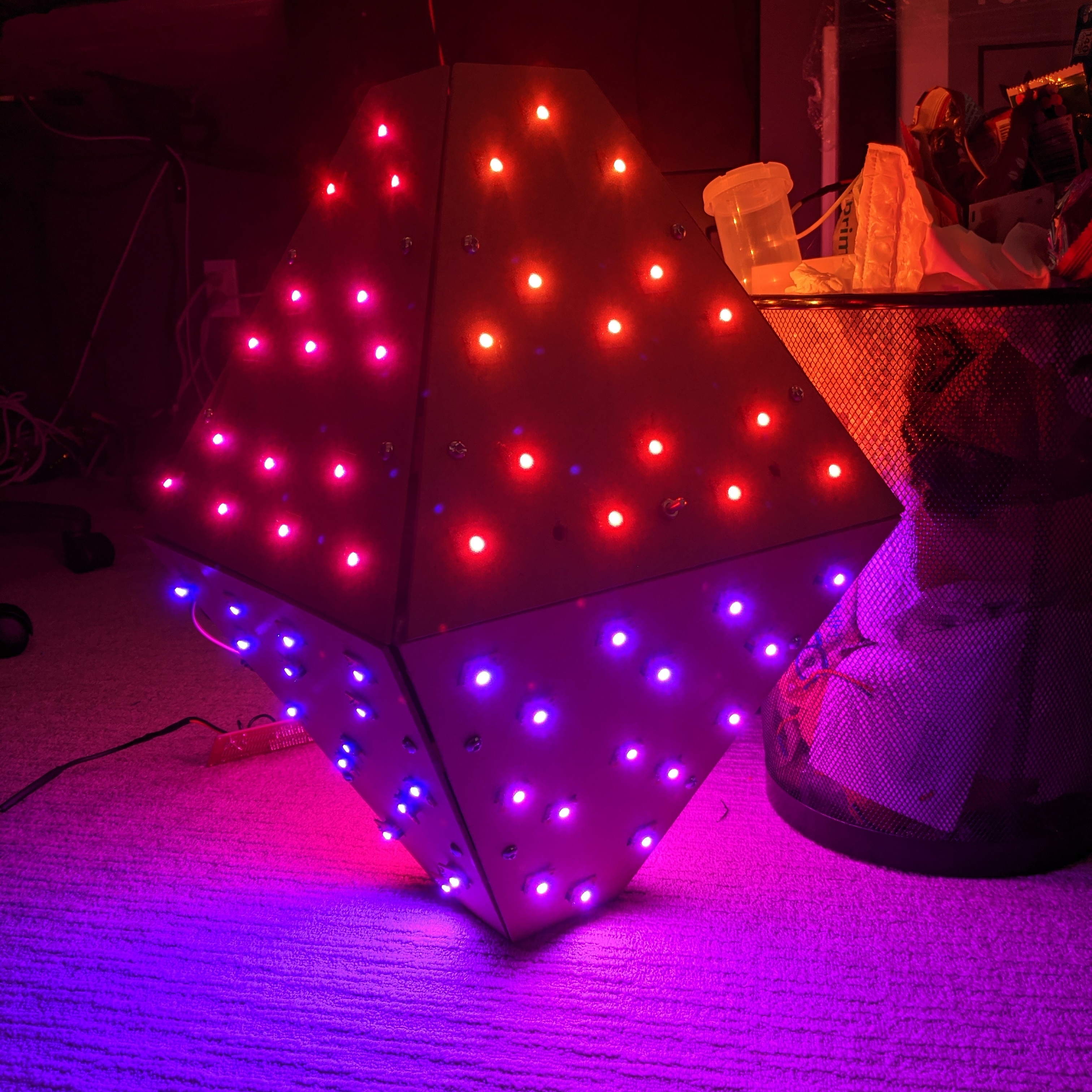
My project is an octahedron with 15 LEDs on each side, in 3 rows. 7 LEDs on the bottom, 5 in the middle and 3 on top.
How would I map this? I
Hi all,
I’m new to this and not really familiar at all with how to code this.
My project is an octahedron with 15 LEDs on each side, in 3 rows. 7 LEDs on the bottom, 5 in the middle and 3 on top.
How would I map this? I
Hey Nick!
I think I can envision the layout, but to make a map, you’ll need to compute the position of each pixel in 3 dimensions, as well as know how it’s wired so you can map the pixel index into each (x, y, z) coordinate.
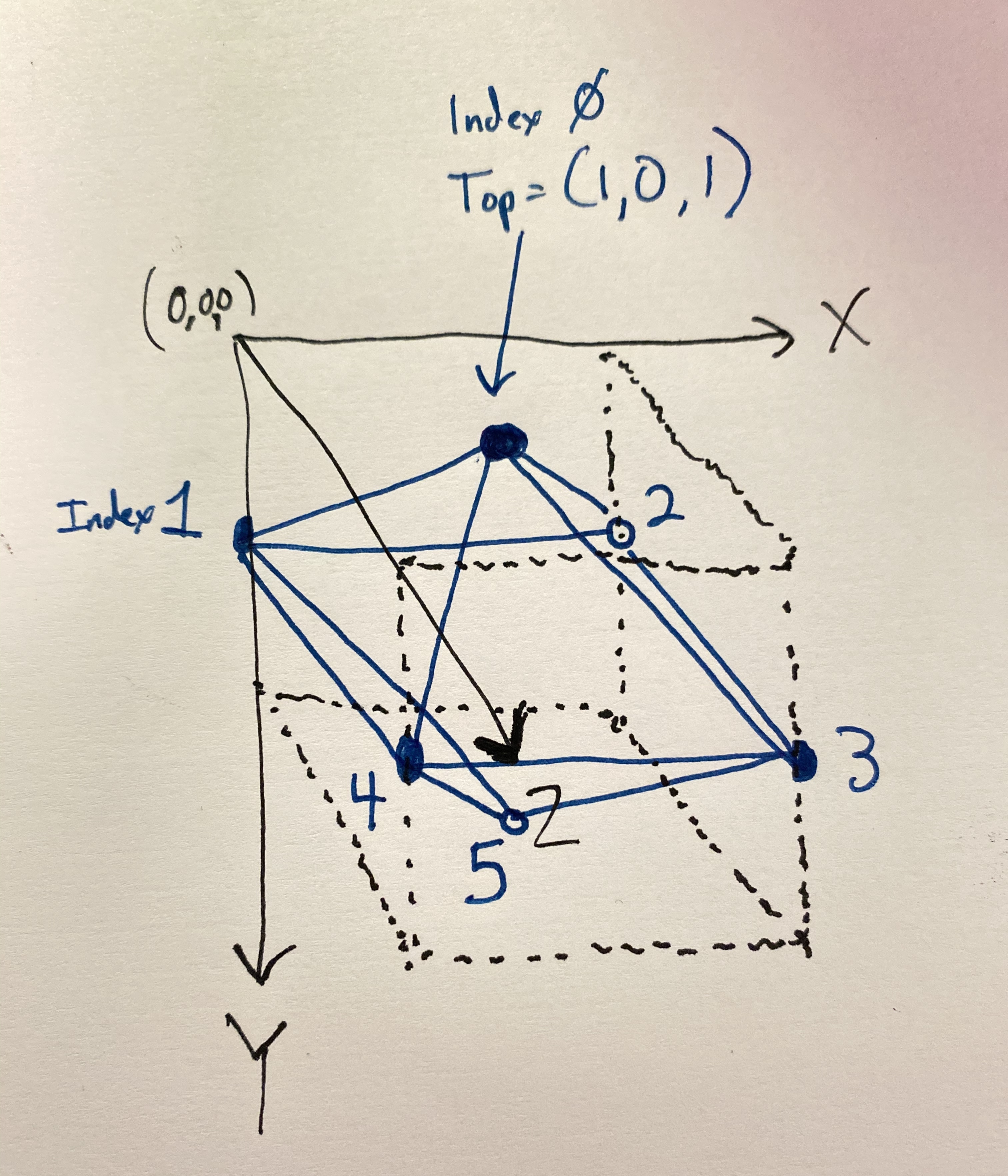
Here’s an example. Imagine an octahedron with one pixel at each vertex. Looking at it from above, I’m pretending that the wiring starts with the first pixel (index 0) is the one on top, closest to my point of view. Pretend it’s now wired to go to the rear left, clockwise around the middle section (pixel indices 1, 2, 3, and 4), and the last pixel is the vertex at the bottom, index 5.
Pixelblaze will scale these coordinates to have each axis go from 0 to 1 anyway, so I’ve chosen to think of the dimension in each axis from 0 to 2 to help me visualize it.
In this simple 5-pixel example, here’s the resulting map. Notice how the first entry in the map is pixel index 0, the first one wired.
function (pixelCount) {
  var map = []
  map = [
    [1,0,1], // Top
    [0,1,0], // Back left
    [2,1,0], // Back right
    [2,1,2], // Front right
    [0,1,2], // Front left
    [1,2,1]  // Bottom
  ]
  return map
}
Obviously yours is going to be much more complicated, having 120 mapped array elements. That’s why you might chose to generate the coordinates in the map javascript, instead of computing and entering them explicitly as in my example. I would make a helper function that can generate a portion of the overall map for any one of your 8 edges, given the start and end coordinates for each edge. Mapping in 3D space is always a challenge for me to rattle my brain looking for the old highschool algebra required. I hope this gives you a bit of a head start!
The payoff is great though: If you get it mapped, you can use any other 3D patterns people have shared in the pattern library.
I was re-reading your message and I think I misinterpreted that your LEDs are along the edges, when I now think you’re saying they’re on the faces, right?
As I re-envision your layout this way, can you describe or share a diagram of how you’ve wired it so I can brainstorm a map generator?
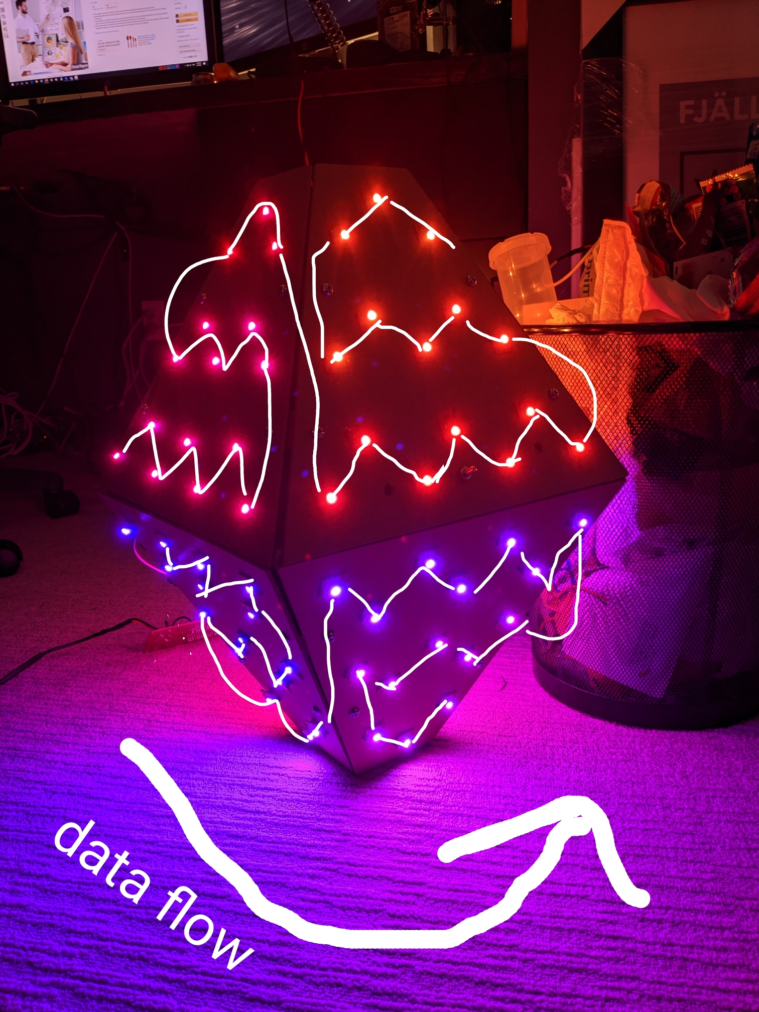
Here’s how it’s wired. Data flows from bottom left to top right. This is how the top portion of the octahedron. The bottom panels go from bottom right to top left.
Hi @nickbeaulieu,
Are each of the 8 faces identical? Is this machined or laser cut? If so, then you probably have coordinates for each point, at least in 2D.
With that in hand, and given that each face is identical aside from its position/rotation in 3D space, you could transform the 2D coordinates for each face.
This article has a great explanation of how you could do that, along with functional example code. In fact, the renderer for the pixel map uses this!
Getting all of the angles and translations could be a bit tedious, but having a live preview should help!
You can also use other 3d tools or pixel mapping software to model and generate your map, and then convert it to a set of coordinates.
Thanks  I’ll take a look at that shortly. And yes, you’re right, each face is identical. Each panel was laser cut for the placement of each LED.
So this is what I’ve come up with:
function (pixelcount) {
var map = []
map = [
//side 1
[100,25,0],
[50,125,-100],
[100,225,0],
[50,325,-100],
[100,425,0],
[50,525,-100],
[100,25,100],
[50,125,200],
[100,225,100],
[50,325,200],
[100,425,100],
[50,525,200],
[100,625,100],
[0,525,300],
[-50,425,400],
[0,325,300],
[-50,225,400],
[0,125,300],
[-100,225,500],
[-150,325,600],
[-100,425,500],
[100,625,0],
[0,525,-200],
[-50,425,-300],
[0,325,-200],
[-50,225,-300],
[0,125,-200],
[-100,225,-400],
[-150,325,-500],
[-100,425,-400],
//side 2
[0,700,0],
[-100,675,-100],
[-200,700,0],
[-300,675,-100],
[-400,700,0],
[-500,675,-100],
[-600,700,0],
[-500,650,-200],
[-400,625,-300],
[-300,650,-200],
[-200,625,-300],
[-100,650,-200],
[-200,600,-400],
[-300,575,-500],
[-400,600,-400],
[0,700,100],
[-100,675,200],
[-200,700,100],
[-300,675,200],
[-400,700,100],
[-500,675,200],
[-600,700,100],
[-500,650,300],
[-400,625,400],
[-300,650,300],
[-200,625,400],
[-100,650,300],
[-200,600,500],
[-300,575,600],
[-400,600,500],
//side 3
[0,0,0],
[-100,25,-100],
[-200,0,0],
[-300,25,-100],
[-400,0,0],
[-500,25,-100],
[-600,0,0],
[-500,50,-200],
[-400,75,-300],
[-300,50,-200],
[-200,75,-300],
[-100,50,-200],
[-200,100,-400],
[-300,125,-500],
[-400,100,-400],
[0,0,100],
[-100,25,200],
[-200,0,100],
[-300,25,200],
[-400,0,100],
[-500,25,200],
[-600,0,100],
[-500,50,300],
[-400,75,400],
[-300,50,300],
[-200,75,400],
[-100,50,300],
[-200,100,500],
[-300,125,600],
[-400,100,500],
//side 4
[-675,25,100],
[-625,125,200],
[-675,225,100],
[-625,325,200],
[-675,425,100],
[-625,525,200],
[-675,625,100],
[-575,525,300],
[-525,425,400],
[-575,325,300],
[-525,225,400],
[-575,125,300],
[-475,225,500],
[-425,325,600],
[-475,425,500],
[-675,25,-100],
[-625,125,-200],
[-675,225,-100],
[-625,325,-200],
[-675,425,-100],
[-625,525,-200],
[-675,625,-100],
[-575,525,-300],
[-525,425,-400],
[-575,325,-300],
[-525,225,-400],
[-575,125,-300],
[-475,225,-500],
[-425,325,-600],
[-475,425,-500]
]
return map
}
Is there any way of streamlining that?
@nickbeaulieu,
That looks pretty good!
Keep in mind that it will normalize the height and width, but that looks like an octahedron!
Since you are doing straight coordinates, you don’t have to write a function, you can just have the array, but it’s already done and working.
eg these are equivalent:
function(pixelCount) {
return [
[1,2,3], ...
]
}
and
[
[1,2,3],...
]
You might want this awesome XYZ sweep pattern by Roger Cheng to see if everything is mapped up right:
Its on the pattern site called “RGB-XYZ 3D Sweep” here:
https://electromage.com/patterns/
You might have to page around a bit to find it.
cool, Thanks. I loaded that up and it seems that the blue works, sort of. It goes down one side and up the other. the green and red don’t quite work right.
When I put in the coordinates, do I have to put them in order of the direction the data flows?
Yes, the order of the coordinates in the map should match up with the pixel wiring.
Aww crap. Well that’s gonna be fun  thanks for the help
  I’ll go and make sure they’re all in order and see how that goes.