I’m new here on the forums and to PixelBlaze and I’m hoping someone(s) can help me out with some wiring ideas.
I would like to create an illuminated set of Mickey Mouse ears for a friend, with lots of LED animation based on randomness and touch-pad inputs. The general idea is to use 2 strips of LEDS, both originating from the middle, and covering the circumference of each ear is about 10 inches of LED strips. I want to have the controller in the center, with a strip expanding out over each ear.
Additionally, I’d like to have 5 or 6 metal pins attached to the ears such that the user can touch them, initiating a pattern based on the pin. E.G., a flag pin when touched would initiate a Red/White/Blue pattern on each strip for a period of time. This person also loves the artist Prince, so I have a metal Prince broach attached, and would love that to initiate a Purple animated pattern display. I also have a pin for their University (JMU) and would like it to display the school colors when pressed.
Also a pin to dim/blank the output. If no pin is touched, I’d like to have a suite of random animations/patterns keep the mood moving!
Can anyone please help me get started on this? How do I go about connecting 2 strips and the touch sensors? I figured the software would easily follow once I can get it wired up! I plan on running this from a LiPo battery as well.
May thanks to any/all who can get me going!
Thank you
Bruce
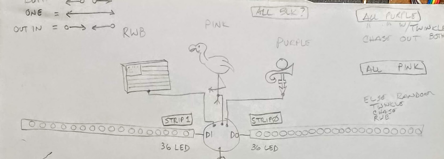
Here’s some photos and a really rough sketch of the physical idea. I was thinking of using an Arduino based device, but I’d like to use the PixelBlaze if possible.
I think your project is quite doable. While the current Pixelblaze v3 Standard has 5 touch capacitive inputs, I haven’t made a project using them yet. I haven’t seen any great example code for it yet. I do know that using the variable watcher with touchRead(pin), you’d be able to figure it out quickly. My biggest unknown is whether a ground plane is necessary, and if so, how large to make it.
I did want to offer more help though to the part about wiring up the LEDs on the ears. Thanks for the pictures - I love the 144/m strips there.
I noticed on your diagram that there’s a circle, ostensibly your controller, that connects to the touch sensor pins and the two strips. It has labels DI and DO, so I just want to clarify that you can only use typical addressable LEDs if you supply data to the Data In (DI) pin on the LEDs. You can’t wire a controller to DO and get pixels to change.
With that in mind, you have 3 options:
(My recommendation) Place the Pixelblaze at the beginning of one ear, or run a short 3 or 4 wire ribbon cable to the first pixel over the person’s ear from wherever the controller is located. Then also wire a short ribbon cable between the two Mickey ears (from DO of the first to DI of the second ear). If you want patterns that are symmetric, reverse one of the ears’ pixel indices in software.
Take the single data-out from the Pixelblaze and solder it to both DIs on both ears near the center. All patterns will be mirrored and symmetric, so this might be a constraint you don’t want.
Use a Pixelblaze Output Expander to take the Pixelbalze’s single data output and create two independent data-outputs. Assuming the DI for both strips is in-between the ears, this keeps wiring centralized but doesn’t force pattern symmetry, so you could still light up one ear without the other.