Hi Team - I recently got a Pixel and Sensor expansion board and have been having lots of fun with my art project. I recently integrated a 10kOhm potentiometer into the analog input poles to act as a dimmer, using the 3.3v, GRND and one of the 5 input poles. this worked a treat once i tuned the software.
I then tried to add a second potentiometer of the same kind into this system to act as a mode selector for different program displays. However, this appears to have overloaded the sensor expansion board as a puff of smoke occurred and it is no longer recognized by the pixel. i rechecked to make sure all the wires were connected to the right poles; they seemed ok.
I’m wondering where i went wrong here. wrong potentiometer? any ideas?
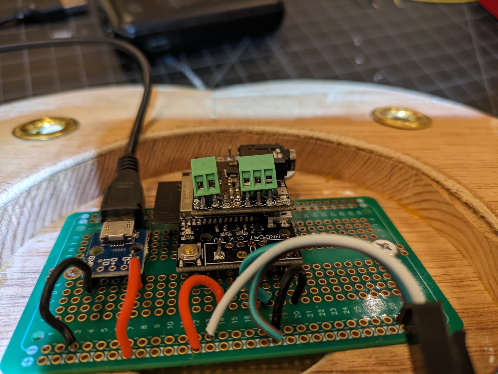
thanks for the reply! I soldered in a few screw terminal blocks to handle multiple wires. i’d thought perhaps there might have been a short but it’s not super clear if that’s the case. regardless i’ve ordered a couple more expansion boards. maybe i could try some different potentiometers, too. the ones i did get were kinda cheap and did not have the most pleasant feel to them. maybe someone here has a good recommendation? thanks in advance (-:
Oooooh no! The red & yellow wires should go to +3.3v and ground (or vice versa). The “middle” connection on a potentiometer, your black wire in this case, almost always goes to the analog input. I can see how the non-standard wire colors caused some confusion!
Oddly enough, the wire colors shown in the picture on the Amazon page are what I would expect.
OMG @Irwin thank you for noticing this!!! i am not so familiar with how potentiometers are made and so i was just trusting the colors of the wires (a crapshoot at best since i’m colorblind). thank you so much for the help, i’ll try this again and hopefully have something more fun to demo when it’s done.
Yeah usually the pots center tap is in the middle, that’s the variable resistor part that will have between zero and 10k resistance to either side, with the inverse to the other. Makes a nice voltage divider. If you have a multimeter the two outside connections should measure 10k) or whatever the pot value is) no matter where the pot is turned.
That 10k is high enough that it’s not going to draw a lot of current from the board. It if you connect the center tap and either side to power it could be shorting everything with zero ohms if the pot is turned all the way to one side, and poof goes the magic smoke.
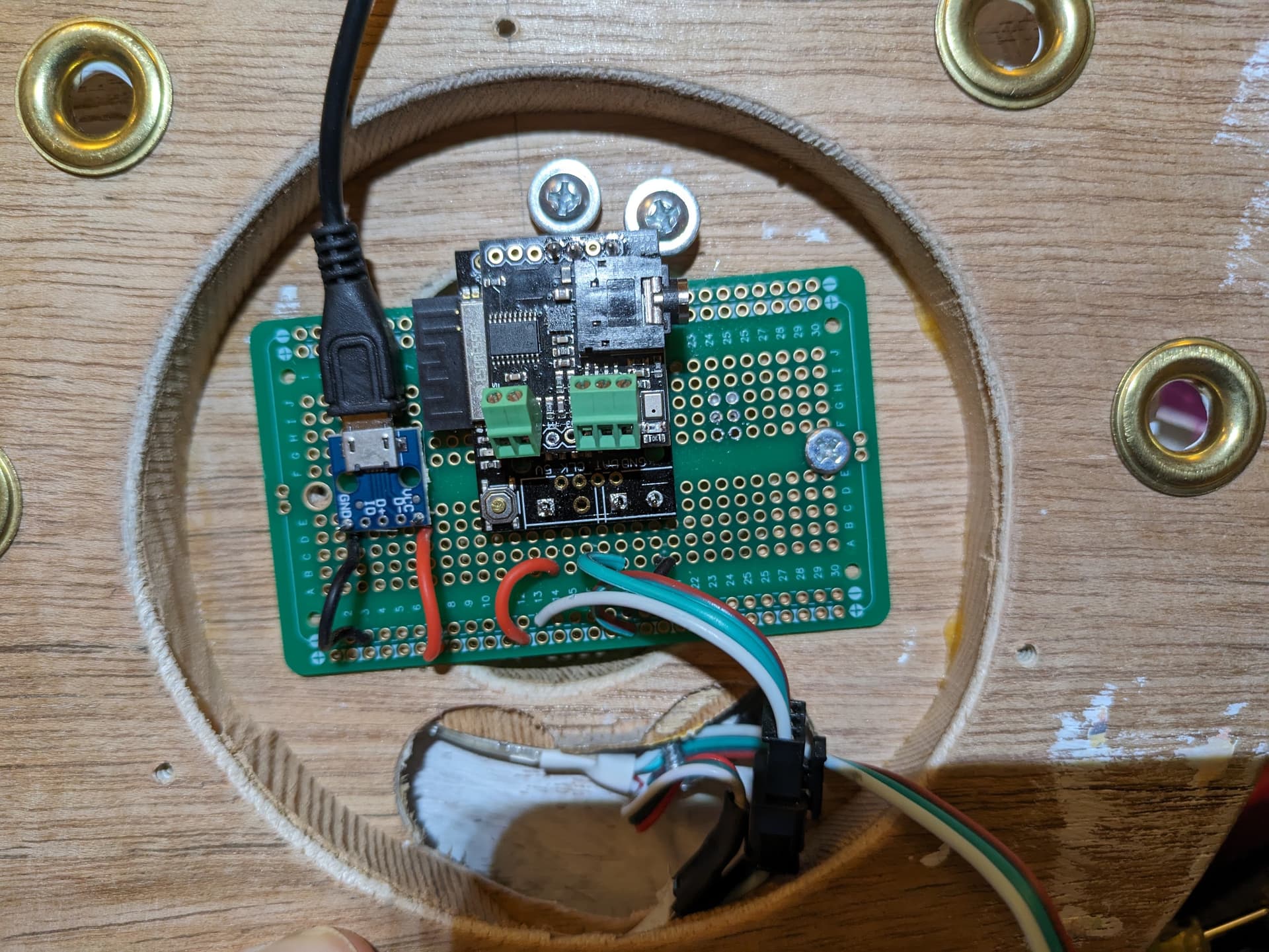
Btw I don’t see where damage has occurred. There’s a small inductor that might have taken too much current if there was a short. That’s going to take some fine soldering work to repair though.
You could try bringing 3.3v from the expansion header over to where the analog inputs are. That would bypass the inductor and might bring your board back to life.