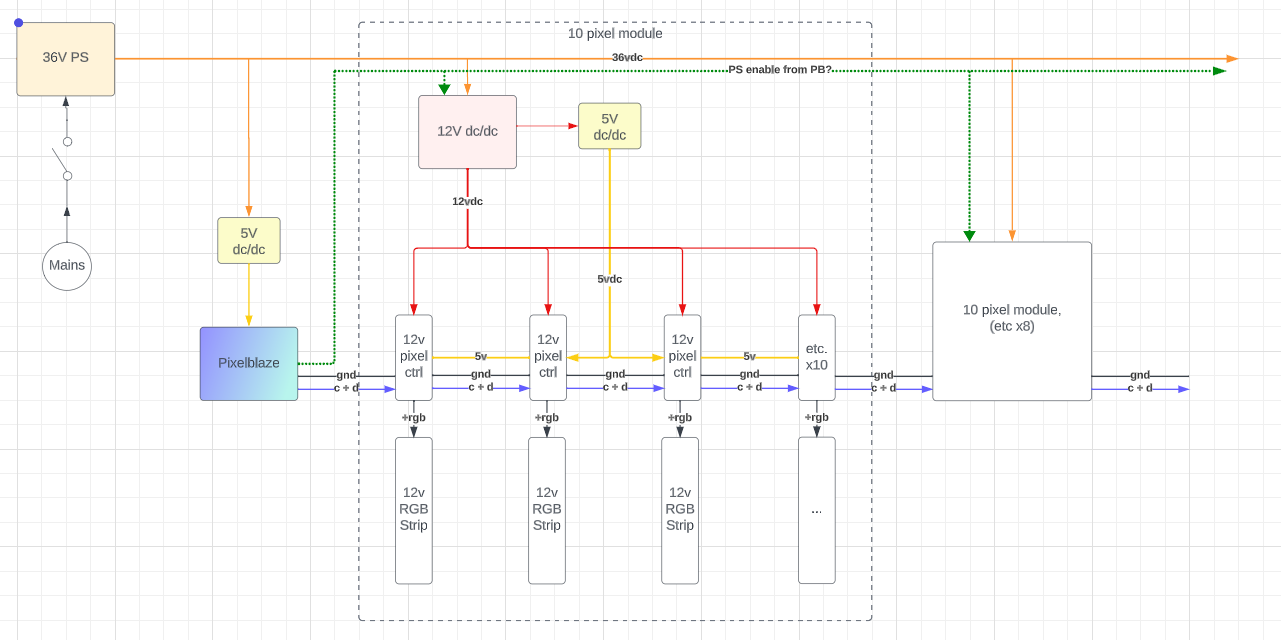
I’m running into a problem with this art. This piece consumes a lot of power. I’m using these RGB controller boards that I got from China that act as a “pixel” - they consume clock, data, and 12V, and output 12V PMW RGB into an analog RGB strip, essentially turning that entire strip into one “pixel”.
The problem is this - when I give it power, the pixel controllers get a lot of noise on their clock and data lines before the Pixelblaze has a chance to boot up, so their initial state is some random (usually white) color. Pretty often the combination of all these random initial states is enough to trip the main power supply OCP, and then it resets in half a second. The more that happens, the more sensitive the PS is to tripping, and so it thrashes, flashing white which is the opposite of what I want. The PS is the largest I could reasonably find, and it works fine if it survives powering up.
I’m thinking of a few routes to address it. One is to tap into the on/off switches of all the 12v converters and control that with the Pixelblaze, so that they stay off until the PB is already outputting stable pixel data. This route would be time consuming and likely error prone.
The other is to somehow mimic a signal of all “black”, or rgb(0,0,0) as the default signal until the PB boots up and overrides that. I’m hoping, doubtfully, that just grounding clock and data is the same neopixel protocol for all black pixel data. Do you know of a way to produce all black pixel data immediately upon getting power?
In either of these cases, I would need some signal from the Pixelblaze that it’s ready to go, either to override the all black data or to enable the 12v dc/dc’s. What’s the best way to do that? I suppose I could add a digitalWrite into the render function of every pattern, but is there an easier and more efficient way?
Can you somehow make sure that the Pixelblaze is already up? I’d need to see more about your install wiring and how you plug it in and turn it on.
Separate power switch for PB vs power supply
Power PB from a USB charger directly off the main 110VAC connection, and plug it in first.
What 36V PS do you use? Some have an "EN"able, remote or dimmer connection, and you can use some simple delay circuits to enable it 5 seconds after mains power has already booted PB.
The problem with putting a small resistor on the data or clock lines to keep the data at 0 (which is indeed black) is that you need to disconnect it at some point. I guess a small digital switching circuit could be adapted to disconnect the ground shunt when the status LED is solid.
1, 2 - I did consider that… It’s going to be installed at the Oregon Zoo for the next two months, so I’m trying to minimize its accessibility to the public, just a power switch for zoo staff to use. The rest of it is out of reach.
3 - I looked, unfortunately there is no remote input on the PS. Very basic. Though since you mention it, I wonder if I can find some sort of off-the-shelf 110v delay module. Put the PB before the module and PS after it.
I’m probably going to add a USB battery pack just before the PB, so if the PS does trip, the PB stays on through it. Two small problems I can think of, 1) If they shut down the art long enough to drain that battery (36 hrs?) then I’m back to square one. 2) If I need to reset the PB for some reason, it’s no longer as simple as a power cycle, I’d have to find a ladder and get up to it. Or can you trigger a reset through the web UI?
I did consider after the original post that I don’t actually have to simulate an all black signal, I just need to prevent the receivers from getting all that noise on power up, which should just be a matter of grounding clock and data until the PB boots. Which, to your point, would be a matter of having a circuit that disconnects the shunts. Good idea with the staus LED, I didn’t consider that.
The PS is rated for 1300W but I highly doubt it… it couldn’t be more than 900W because I have a 25A circuit breaker after the PS which has never tripped. Suffice to say though more than 3A on the in side. But that second one will do the trick! Good find.