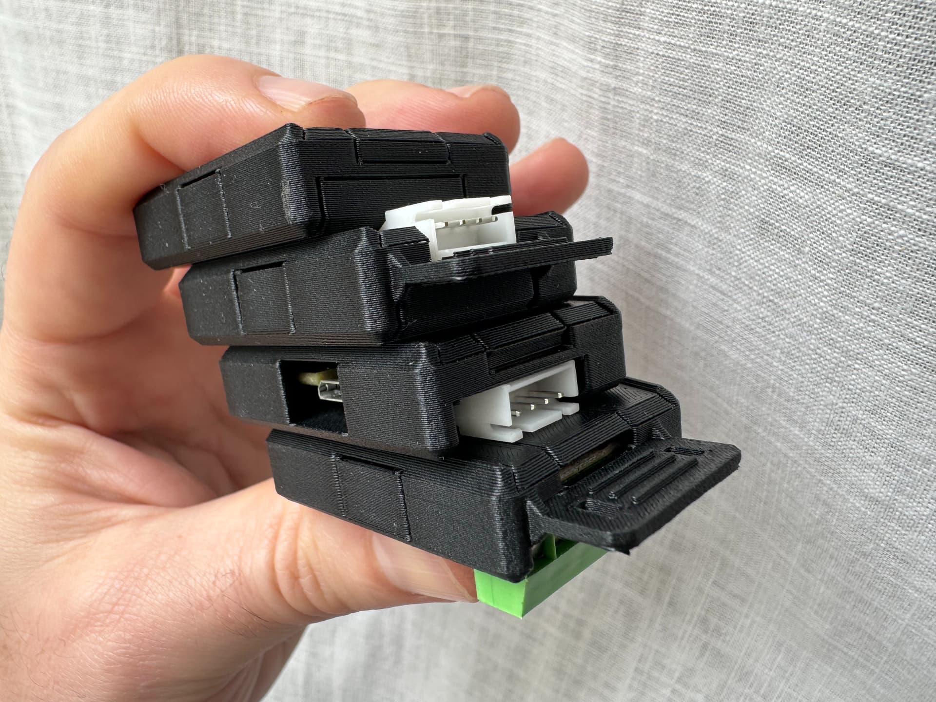
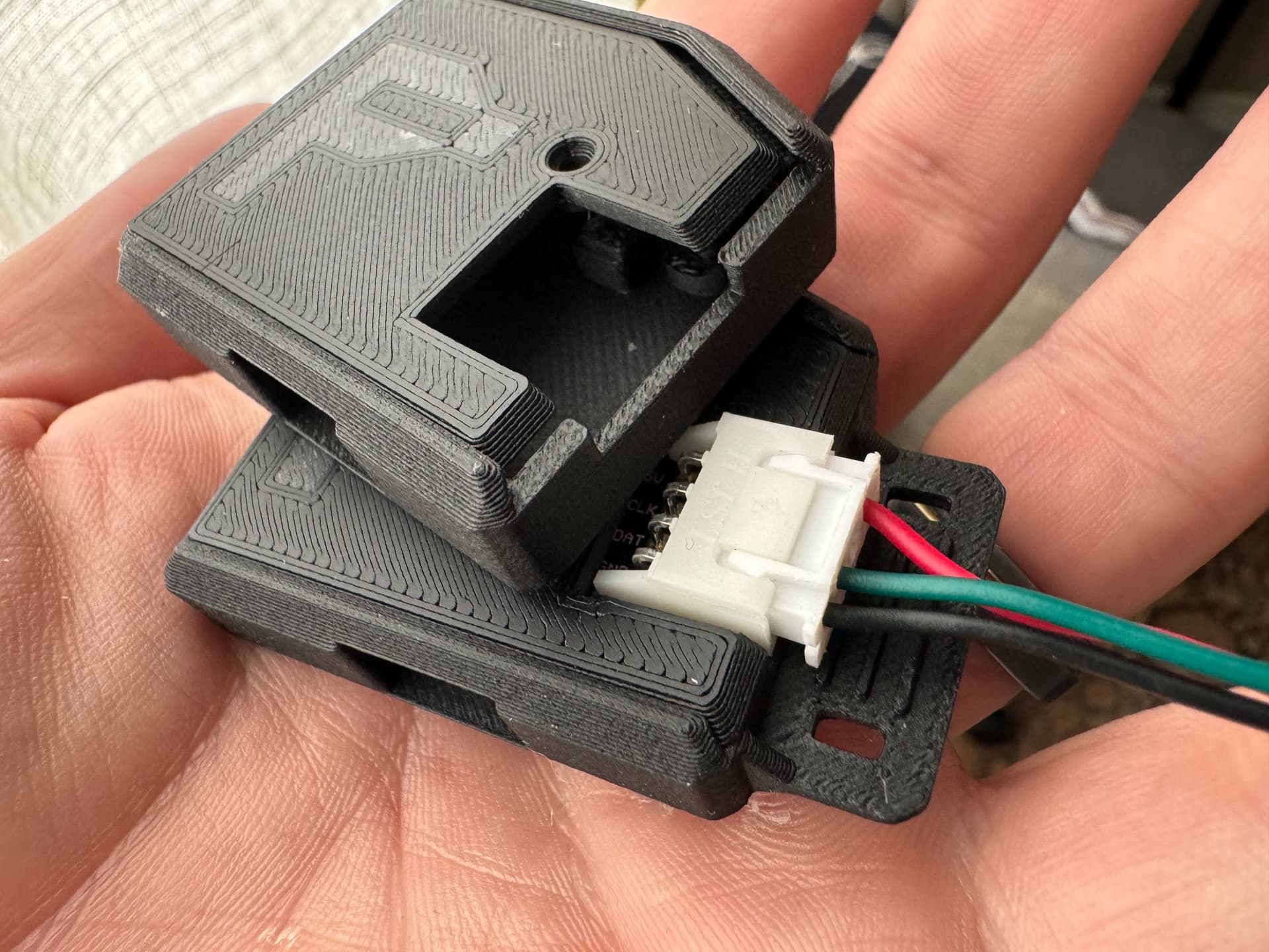
The XH-on-bottom or “ready-to-run” cases have holes for an XH on the bottom of the PCB and the USB connector. They’re mostly for our upcoming “no soldering required” offering: a Pixelblaze Standard with a JST-XH connector pre-soldered to the bottom of the board. Soon we’ll also be adding a bunch of adapters to get from this JST-XH connector to any LED strip’s black JST-SM connector (any pin ordering) - no more re-screwing the screw terminal for each type of LEDs.
Each comes with or without an output strain relief shelf for use with a zip tie.
All four variations can snap into our new mounting cradle. The cradle provides screw holes, zip tie slots, a USB strain relief platform, and the ability to add an LED output strain relief shelf to the versions that don’t have one built in.
As with the previous Pixelblaze + Sensor board case, we’re releasing the Fusion 3D model and single-material print files on our GitHub. Personal remixing is encouraged, and commercial remix is allowed for Pixelblaze products if you shoot an email to support@electromage.com first.
I love JST-XH connectors for board to wire connections, I use them in most of my builds. There’s also JST-XA, which is similar to XH, but provides locking connectors: https://www.jst-mfg.com/product/pdf/eng/eXA-WB.pdf
The video just popped up on my YT and incredible. I’m on LED hiatus after the cube and the artcar but got some things cooking up and super happy to see this has been finalized and released. Thanks folks for the hard work! Excited to pick a few up!
Excited to hear that!
I hope you’re not horrified by my answers…
In my use cases so far, I’ve just used a bunch of screw terminals. I use the included larger-size screw terminal for the connection between the PB and the output expander, then I found some very tiny screw terminals that fit the outputs on the other end. I power my strips separately, and haven’t used any of the fancier ones that require the clock line, so I just solder two tiny 4-pin screw terminals side by side across the 8 data outputs, since that’s all I’ve needed.
Totally reasonable! FYI the cases will probably be optimized for people who solder their output expander to their PB somehow, since the need for a custom case is usually about keeping the size down.
For my other builds where I’ve kept things separable (and yeah, I’ve done PB → OE via screw term before, just like you!) I commonly pick an enclosure from Amazon. I like the waterproof ones with clear snap-shut lids. I commonly make a wood platform that mounts into the screw boss holes in those so I can remove things to service them.
To set expectations, I probably won’t have the weeks it will take to finish the next design for at least a month, so if your project can’t wait, I’d advise you move forward with one of those for now!