Hi. I would like to know what the DC voltage is suppose to be reading off each address pin on the output expander board? I tried looking over documentation but I can’t find any regarding this or I didn’t look hard enough.
My lights are 24 volts and are wired directly through 3 pin waterproof connectors to the power supply.
I have my pixel blaze plugged into a USB wall adapter and the lights are on both the PB and Output expander. When I try a DC volt readout from pin to ground, I get no reading. Hence why I think the lights are not turning on as they are receiving no signal.
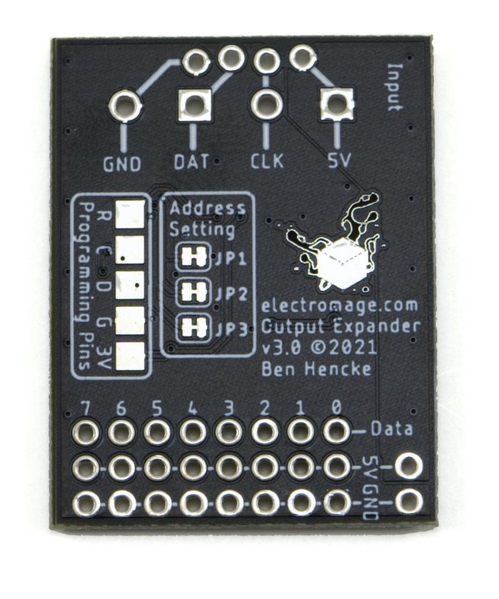
So I can help better, can you clarfy what you mean by “Address pin”? There’s address jumpers on the back which may be confusing me about what you’re looking to measure.
In general, you can’t use a multimeter to tell if data is coming through a data pin successfully, because it might be sending mostly "0"s, which would be 0V.
Can I confirm that:
You have all four lines wired between a Pixelblaze and the expander (GND, DAT, CLK, 5V)?
You have a common ground connection between the power supply and the ground on the Pixelblaze or expander?
You’re only wiring the Data out lines from the expander to the strips - none of the 5V pins
You’ve configured the Output Expander in the Setup tab of Pixelblaze, and used the auto-index button after assigning the number of pixels to each channel?
That should cover the common mistakes I’ve seen here on the forums!
Check out the docs here and here if you haven’t already seen these.
Thanks for the help. I figured out the problem being trying to power the board off a wall outlet.
When I powered PB and the expander board with solid 5vdc from a power supply, I was able to read about 2vdc on the data line and thus the lights lit up.
In my experience I would say you typically want to meter out at 1vdc or more on a data line.