Pixelblaze control of PC case fans with RGB LED
PC case cooling fans are sold with LEDs embedded in various ways:
- Fixed: This is the easiest and cheapest way, a single color that lights up whenever the fan has power.
- Self-contained: Colorful LEDs but controller is embedded within.
- JRGB style: Color can be controlled but all LEDs will be the same color (not individually addressable.)
- JRAINBOW style: individually addressable WS2812-style RGB LEDs.
JRAINBOW style fans may be controlled by a Pixelblaze in place of a PC. Such a project’s difficulty level depends on how the manufacturer decided to implement its wiring.
- Two separate connectors: one connector for controlling the fan, and a separate connector for LED control. Usually found on individually sold RGB fans like this CPU cooler solution example on NewEgg. Separate connector makes it easier to connect to a Pixelblaze.
- Single integrated connector combining fan and LED control, usually plugs into a mystery box that combines power input and JRAINBOW LED interface to the computer motherboard. Usually found on RGB fan multipacks like this example on NewEgg.
A Pixelblaze can connect to the input port of that mystery box, which will suffice for some projects. But if not, we have to dig deeper.
The rest of this post is my experience “digging deeper”, which is an intermediate level electronics project requiring access to tools like an oscilloscope or logic analyzer. I describe how I worked with a specific product, with some generalizations that I hope is helpful for others who wants to do the same thing to a different product.
The subject of my digging is the Asiahorse Magic-i 120 V2 which is a trio of fans that plug into a mystery box hub. The hub has a connector for PC power supply and a JRAINBOW connector for the motherboard. This bundle also included a remote control, which I wanted for this project because independent operation meant there’s no risk of damaging a computer if I should make any mistakes.
The proprietary fan connector has six wires. Doing the easiest thing first, I probed for electrical continuity on the hub between its output fan pins and its input power connector. A PC accessory will use one of the following types of power plug:
In the case of my hub, there was electrical continuity for three of the six pins corresponding to +12V, +5V, and Ground. Three down, three to go. What are the remaining three wires? Here are some candidates:
- Fan Control: (Optional) one or none of the following:
- High side: Fan motor may be internally connected to the ground line, leaving the high side to be externally connected to +12V via a power transistor. May be used for on/off control or PWM modulating the transistor for speed control. Can connect directly to +12V which will run the fan at max speed whenever there’s power.
- Low side: Same idea but reversed. The motor is internally connected to +12V and this line allows external power transistor to connect to ground. Can connect directly to ground which will run the fan at max speed whenever there’s power.
- PWM: Neither of the above. Instead of leaving high or low open for connection via external power transistor, a suitable power transistor is built into the fan itself. Speed is controlled by an external 25kHz PWM signal. Typically found on CPU cooling fans. OK to leave disconnected, as absence of PWM signal typically default to running the fan at some preset speed. (That may or may not be 100%.)
- Fan tachometer: (Optional) an open collector/open drain line for a square wave whose period corresponds to fan speed. OK to leave disconnected if we don’t care about monitoring fan RPM.
- LED Data In: (Required) LED control signal. Likely WS2812 style directly forwarded from motherboard through hub, but possibly translated by hub to a different LED type. OK to leave disconnected if we don’t want to control integrated LEDs. (But if so, why are we even here?)
- LED Data Out: (Optional) LED control signal that comes out of the tail end of the string of LEDs, allowing multiple devices to be chained together. When absent, we won’t have a way to chain multiple fans together and controlling them would require the Pixelblaze output expander. OK to leave disconnected if we don’t care about chaining.
To narrow down my candidates, I connected those three unknown lines (plus a fourth wire for ground) to my logic analyzer acting as analog waveform capture tool. Connected to the bundled hub, I powered it up and used the remote control to command a solid color. This activity generated the following trace:
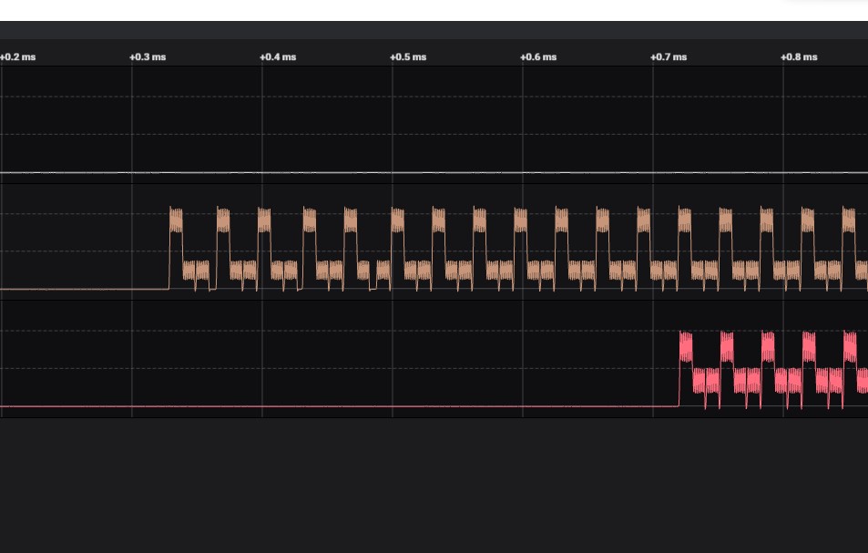
The top line in white stayed low, so it might be either low-side fan control or fan tachometer in the absence of a pull-up resistor. To figure out which, I connected just the +12V and Ground pins. The fan did not move. I connected this wire to ground, and the fan started spinning. Conclusion: it is the low side of fan motor.
The middle brown line showed signs of a digital control signal repeating at regular intervals. The bottom red line showed a very similar pattern but delayed by 12 cycles. I counted 12 LEDs in each fan, so the middle brown line is LED Data In and the bottom red line is LED Data Out. To verify, I connected +5V, Ground, and Data In pins to a Pixelblaze. This gave me control of the ring of 12 LEDs in the hub of these fans.
Having the LED data out line was a pleasant surprise, it meant I didn’t need a Pixelblaze output expander to control this trio of fans. Curiously, the bundled hub didn’t bother using that feature. Every Data In line is wired in parallel.
In order to control these fans separately, I would have to create my own circuit board and chain their data in/out lines together for a Pixelblaze to control.
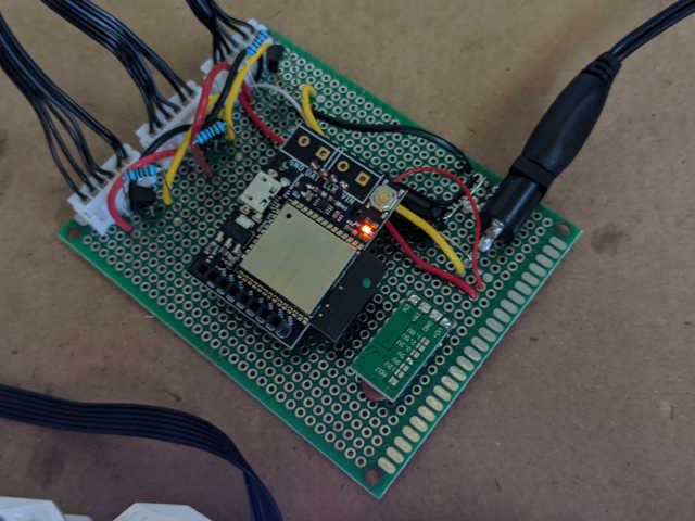
Once that was done, I could control them with the full power of Pixelblaze, including my favorite feature: 3D pixel coordinate mapping. I lashed the three fans at right angles to each other using twist-ties, and mapped them to XY plane, YZ plane, and XZ plane. Here is the contraption running my coordinate test program which sweeps through X axis in red, then Y-axis in green, finally Z-axis in blue. (I have the Z-axis backwards in this video, but that’s a problem with my map and doesn’t affect the electronics focus of this post.)
Here is my pinout diagram for these fans. I have no idea how common this layout is. Perhaps all 6-pin LED fan connectors are laid out this way, perhaps they are all different. I don’t have the money or patience to buy them all and test them. But I hope the information above will help somebody else figure out their own LED fans to use with a Pixelblaze.
