Pixelblaze Pico v3 lights up dim orange, then bright orange, then restarts

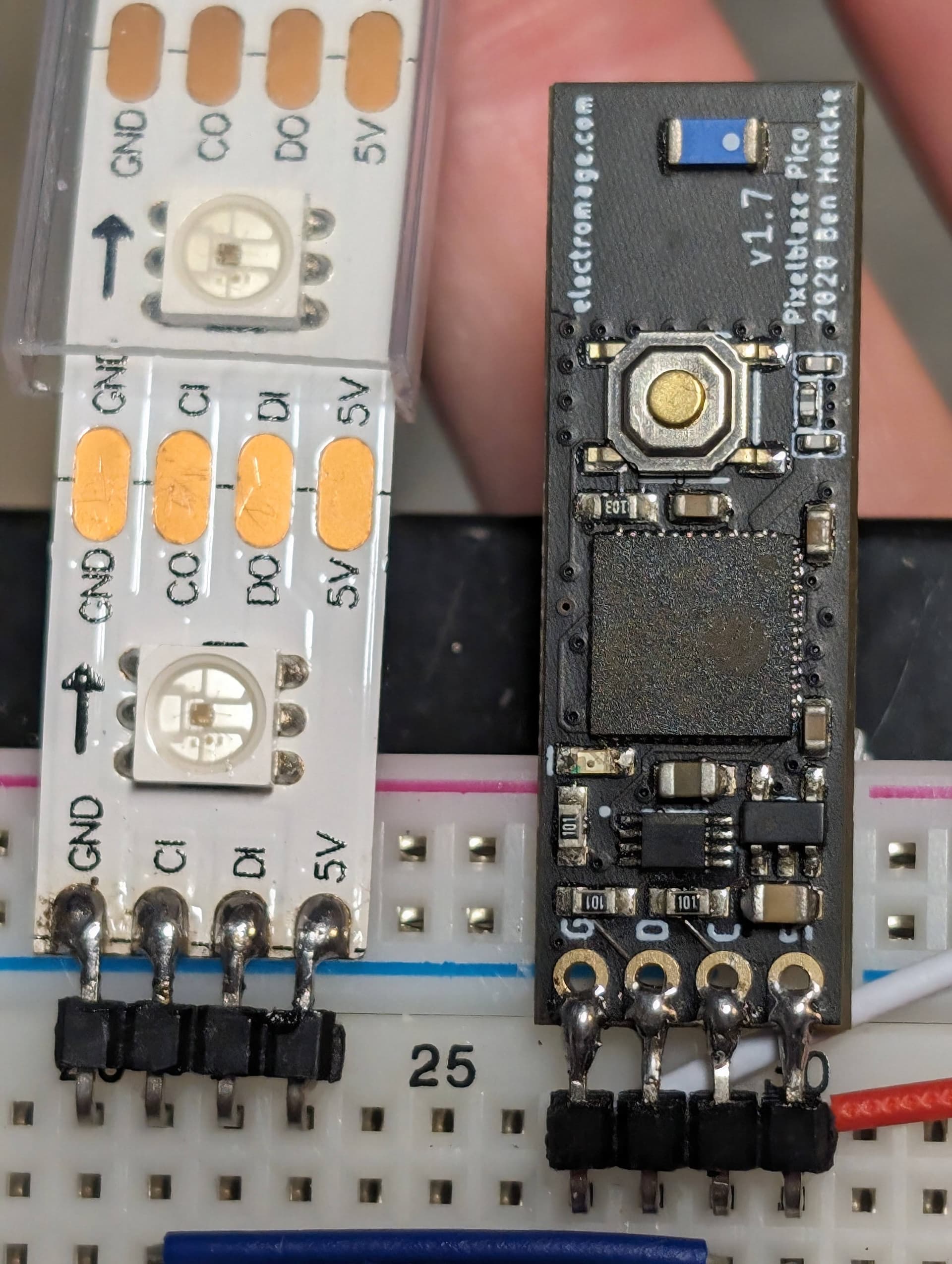
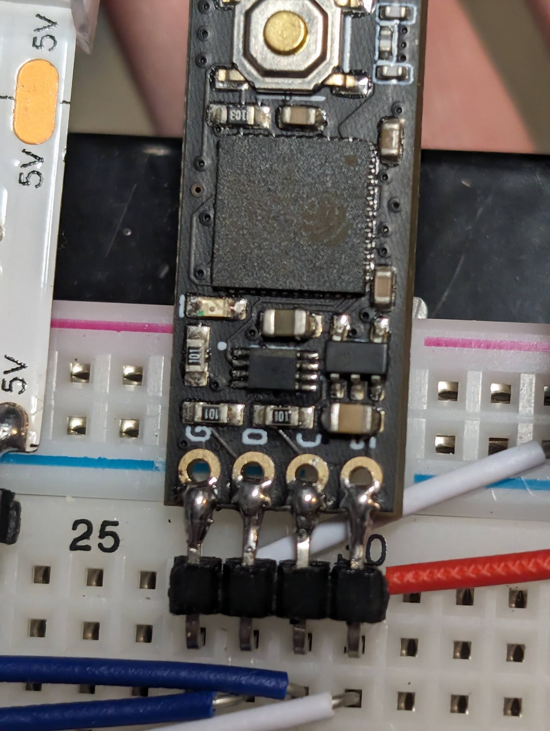
My LED project was on loan to someone, and when I received it back it no longer turned on. After close inspection, I could see that the Pixelblaze Pico inside was briefly turning on, lighting up dim orange, then bright orange, and then restarting after about a second. The device has 312 APA102 LEDs and is fed power at the beginning and end of the LED strip from a 5V 15A power AC adapter. Strangely, if I shine my flashlight at the strips as it turns on, a few of the LEDs will briefly flash on. When I try resetting the WiFi by pressing the button for 5 seconds, the orange light will begin blinking, continuing until I let go of the button before restarting again.

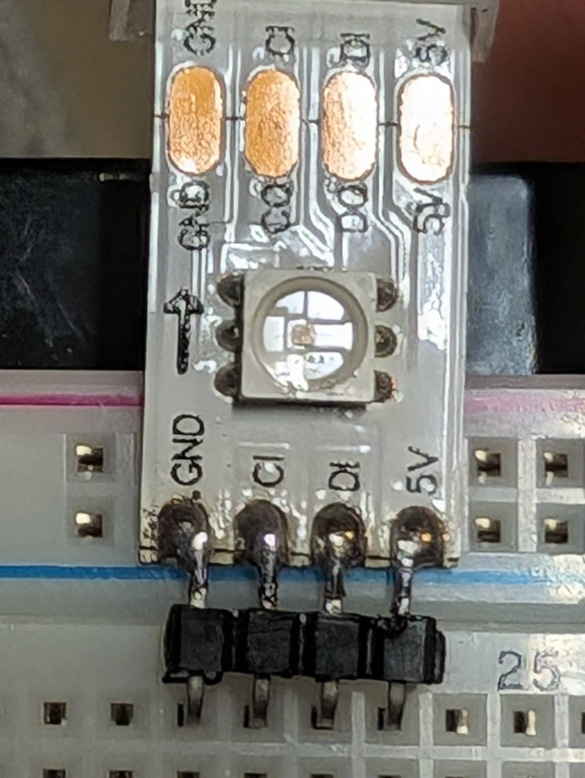
I inspected all of the solder points as best I could without removing each strip from the channels they are installed into, and they all looked intact as they were when the device was originally fit together. However, on the last strip at the end, there is possibly some discoloration (white flex-PCB slightly yellowed) around the SMD solder points of the LEDs.

So these are my questions:

  • Shouldn’t the failsafe mechanism in the Pico disable the LEDs and allow itself to boot?
  • Could this be a case of overheating/burning out some of the LEDs? What symptoms could I look for?
  • What other troubleshooting steps would you recommend?

Try disconnecting the LEDs, just powering Pixelblaze and see if you can get it back up and running. If that doesn’t work, I’d also try another power supply.

If there is a short it might be tripping the power supply. If all 312 LEDs turned on full white, that could also do it (theoretically 18A).

Thanks for responding so quickly! Actually, I plugged it in with a 3A power supply I had on-hand (way underpowered) and the Pixelblaze was somehow more stable–enough that I could reset the WiFi settings and navigate the web interface. I tried turning the brightness to zero and reducing the max brightness and LED count, but they don’t seem to take effect. Sadly, it isn’t stable, and resets frequently at random intervals. While it’s on, a portion of the strip is lit up white. A couple of times it played a little of a pattern (the stock one with all the rainbow sparkles).

It’s possible your big power supply had gone bad, and with LEDs attached your 3A can’t keep up. I’d try to disconnect them and power PB alone, see if you can get it stable.

If that’s not easy, you could try another high current supply.

I’m hoping to try the latter suggestion (high-amp PSU) to avoid desoldering in a tight spot, at least until it becomes clear that the issue lies with my PB. Unfortunately, my PSUs on-hand aren’t in a ready-to-use state, so I have to find time to finish wiring one or temporarily jerry rig another to run the test.

Again, I appreciate the support and will report back after I have more information!

Ok, here’s my follow-up:

With the PB connected to the LEDs and powered with the 3A PSU, the PB was unstable and would occasionally remain on long enough to connect to WiFi and host the configuration interface. Although I was able to change settings and see that they “registered” with the PB in the interface (persisting between restarts), they had no effect the actual LED strip. In this semi-stable state, I was able to observe that the last four segments of LEDs were the only ones that consistently lit up and they always landed on a full white state before the PB restarted.

I ended up disconnecting the PB from the LEDs and testing it with a breadboard and a spare LED strip. The PB was stable without any LEDs connected and, with LEDs connected, was able to display the patterns I tested. One noteworthy difference is that the LEDs in my project are 4-wire APA102 and the spare LEDs are 3-wire WS2812.

This leads me to conclude the problem lies somewhere in the LED series in my project–possibly the data or clock line between the 5th-to-last and 4-to-last LED strips, or any of the other ~100 solder points. I feel like the last few segments lighting up full white suggests the root cause, or at least which points lines I should check first (power, data, clock). Given your understanding of APA102 LEDs, what would you check first?

Sounds like the Pixelblaze is OK, thats good news!

How do you have your Pixelblaze connected to power? Is Pixelblaze on the far side of the LEDs, so that you have Power → LEDs → PB? Ideally you’d have Power → PB → LEDs, or parallel:

Power -> PB
     \-> LEDs

The power at the end of an LED strip is going to have voltage drop and instability (when patterns are displayed) that would definitely interfere with normal operation.

Sometimes adding large capacitors helps smooth out power and increase stability. Like 1000uF or more.

If LEDs or data path was damaged and some turned on full white it can make a system that was otherwise working unstable. It wouldn’t matter what brightness setting was in place, those LEDs could draw a lot of power and cause more voltage drop at the end of the strip, or overload the supply.

Troubleshooting and repairing addressable LEDs can be tricky, especially if your system can’t power everything when they are displaying white and overloading the system and causing resets. You might want to power Pixelblaze and the LEDs separately so that PB isn’t getting reset.

Generally my strategy is to run a pattern that will show which LEDs are responding. Then find and mark the first non-working LED, along with the previous (last working) LED. Remove power, cut out the two LEDs, then splice the strip back together. Repeat until the whole thing is working, there may be other bad LEDs. You can go one at a time, but sometimes a non-responsive LED isn’t to blame, its the previous LED that appears to work but isn’t sending data properly.

If you need to keep the same number and/or length of LED strip, I find it easiest to add a section to the end once everything else is working.

There are a couple of ways the LEDs/strip can fail, with the above method being the most universal of fixes. Sometimes there’s just a small crack in the copper on the strip that can be fixed with a bit of solder. Sometimes the surface mount LED lifts up off the pad and can be very carefully reworked, but I rarely have success with that and it ends up taking more time that cutting out small sections and splicing.

Thanks for the detailed troubleshooting suggestions!

To answer your question, I am powering the PB and the LEDs in parallel. I do not have a capacitor on the power, although I’ve used them in past projects–to be honest, I kind of ignored it and assumed the PB Pico had an SMD cap.

Unfortunately, my further troubleshooting leaves me still scratching my head.

I removed the first segment of LEDs from my project to attempt swapping it with a fresh one (each segment is 13 LEDs long). However, I wanted to test both the old and new segments with the PB on the breadboard first, in case the swap-out was unnecessary. Neither APA102 segment lights up, even though the PB is able to control WS2812s just fine. I made sure to correctly change the settings for the APA102s before connecting them.

Since the clock signal is an obvious difference in these LEDs, I wanted to check if it was working as expected. I flashed a spare Arduino with a simple program to do that–the demo code for FreqCount–and it’s reporting zero Hz. Have you ever seen the clock signal fail before?

Rather than rip my project apart further–searching for a loose LED or lifted pad–I think I’m just going to order a few more PBs to have on-hand (since I have a couple of other projects that need them), and see if a swap out will solve the problem.

It’s possible that the clock circuitry is damaged. Is that the same PB, or a different one?

On a Pico, the resistors for data and clock are near the solder connections, do those look OK?
It’s possible to damage the small traces that wire the soldering holes/edge to the resistor if your iron was too hot or scratched the PCB there. The clock output connects to the top of that resistor, and could be checked with a continuity tester.
The level shifter is the small chip in the middle just past the resistors. It’s worth checking to make sure it’s not dirty or shorted somewhere.

pb pico clock troubleshoot

Yes, Pixelblaze has a small 1uF capacitor but it’s only powerful enough to absorb some high speed noise and keep the voltage regulator from having issues. If power is unstable, it won’t help much, often times something 1000x more is required if there are power issues.

If you have photos of your connections, PB, and LEDs, I might be able to spot something.

Yes, it’s the same PB. Overall, the components looked fine–no signs of escaped magic smoke. My only concern was the 1µF capacitor (I assume) by the 5v hole looked like the solder on one side was a bit ugly. Unfortunately, I didn’t take a photo of that before I reheated the joint and added a tiny bit of solder.

I also confirmed continuity between the CLK hole and the B1 pin on the level shifter, and between the A1 pin on the level shifter and the IO18 pin on the ESP32–they were ok. I traced them by sight with a jewler’s loupe before I realized you published a schematic on Github–thanks to @GeekMomProjects for linking to it from a random thread I stumbled across in my troubleshooting!

You’re probably 100% right about my issues being rooted in unstable power. I was pushing the max brightness and clock speed as high as possible without experiencing flickering (at home). Then, I put it on display in my friend’s hair salon. In hindsight, a very unfriendly environment for digital electronics with all of their high-wattage dryers, clippers, towel warmers, etc.–omitting the 1000µF capacitor would’ve left the PB unprotected.

Since this PB seems like it could still work ok for WS2812 LEDs (and I have a bunch), I’ll probably just reassign it to a project that uses them. I noticed you released a new rev of the Pico with a 6-axis accelerometer, which is awesome!

Here are photos in case they reveal anything:


Pour one out for my (temporarily disabled) Rhombotron!

Finally, thanks again for your time and attention to helping me with this.

2 Likes