PixelTeleporter - virtual LEDs on your computer

Just updated to add the ability to import and export Pixelblaze pixel mapper JSON maps (and fix a couple of minor bugs.) This feature lets you create a displayable object direcly from pixel mapper output.

See the new MapIO example in the repository for details.

2 Likes

Whoaaaaaa this is awesome!

you mention an ESP8266, but would an ESP32 work?

Thanks, nickbeulieu!

There are differences in a couple of libraries, so the ESP8266 code almost certainly won’t work as-is on an ESP32. ESP32 support is on my list, along with Raspberry Pi and a few other things. It’s a week or so out at this point. (I’ve been focused on getting the generic APA 102 protocol reader going at a reasonably high speed. It’s been one of those interesting problems. Even if it never works the way I want on the 8266, I’ve learned enough to make it worthwhile.)

Just updated the core components. See the first message in this thread for more detail. We’re a real Processing library now!

Raspberry Pi support, and FTDI board interfaces for Linux & Windows are next on the todo list. Should be along shortly. (The APA102 reader is stalled at a snail-like 500Khz on ESP8266 – think I’m just going to move on to ESP32 for that one.)

1 Like

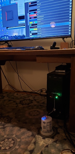
Update to PixelTeleporter v1.1.0 is now up on GitHub. Includes Raspberry Pi serial support, and Linux and Windows support with an FTDI USB->Serial adapter. The best thing about this new release is that, with an FTDI board, you can now hook your Pixelblaze up to the same computer you’re using for the Processing scripts. Details on everything new in the various README files in the repository.

Of course, wired and wireless networks are supported, as are multiple LAN adapters on the server machine. (The server also supports sending Pixelblaze data to multiple clients, and other future oriented features – I’ve got a virtual LED-wiring-over-ethernet experiment on the roadmap.)

Cheers,
Jon
3 Likes

So now we don’t have to connect the PelexTeleporter(esp8266) to the PB as an expander? I’m sorry but my brain is really not getting how these are all connected and setup. Anyone make a tutorial yet?
When you say FTDI to USB are you meaning this http://amazon.com/Adapter-Serial-Converter-Development-Projects/dp/B075N82CDL ? I can’t make it out in your pic what it is. Have a link to what you are using?

My fault for not making the architecture more clear. I’ve been living with this idea for long enough that I kinda lose track of what might not be immediately obvious…

PixelTeleporter comes in two pieces

  • a Server, which hooks to Pixelblaze and sends data to a computer.
  • a Client - the PixelTeleporter Processing library, which receives and displays the data.

Prior versions had only the ESP8266 server, because that’s the first one I wrote and I used it to test everything else. I’ve finally gotten around to writing servers for other platforms: Pi, Linux and Windows. It doesn’t change how things work. It just gives you more choices so you can use the hardware setup that’s handiest for you.

The ESP8266 and Raspberry Pi servers require no additional hardware to talk to Pixelblaze. The Linux and Windows servers require an FTDI or compatible USB->Serial adapter.

The “connect to the same PC you use for Processing” feature falls out naturally from the way the network stack works. The client and server will always think they’re sending data across the net.

But if you run the server on a machine, and give Processing on that same machine the localhost address (127.0.0.1), it will grab the data quickly and efficiently from internal buffers, without anything at all going over the actual network.

There are fairly detailed setup instructions for each server in the README.md files in the individual subdirectories in the servers directory of the repository. And I’ll do my best to answer any questions that come up.

3 Likes

and yes, that’s exactly the USB->Serial adapter I’ve got! It’s been super helpful for any number of projects.

1 Like

It really is an amazingly cool idea and implementation. I’d say “May I ask one more question” but that would probably be a lie. :slight_smile: I ordered the adapter. I have never used an adapter like that can you explain the connection between the PB and the adapter? Is it…

Adapter switched to 5v? or 3v?

Adapter(RX)-------------> PB(TX)
Adapter(TX)-------------> PB(RX)
Adapter(GND)----------> PB(GND)
Adapter(Vcc)------------> PB(3V) or Maybe the 5v pad on the back of the PB?

Is that right and all of them?

Always happy to get more questions!

Set the adapter for 5v. You only need 3 lines – hook them to the LED strip connector on the back of the PB.

Adapter(RDX) —> Pixelblaze(DAT)
Adapter(VCC) —> Pixelblaze(VIN)
Adapter(GND) —> Pixelblaze(GND)

The adapter works with USB 2 or later. Windows 10 will automatically install the FTDI drivers when you plug the adapter in, Linux comes with them installed. For older Windows and others, the drivers can be downloaded from FTDI’s web site.

Here’s the whole setup procedure for the Windows server. Linux is nearly identical, with the addition of a build step.
(https://github.com/zranger1/PixelTeleporter/blob/master/servers/Windows/README.md)

Oh wow, I was off on my thinking. So it’s the led output on the PB to the adapter. Was that the same when the server was the ESP8266? I thought we soldered the header onto the PB and used those pins to connect to the ESP8266… :slight_smile:

I think that is also my mistake in thinking the 8 port expansion board got connected to the header pins on the PB and not to the GND/DAT/CLK/VIN led output from the PB.

I hope I am right that the header pins on the PB are for the sensor board. :slight_smile:

WOW was I off in my thinking. I wonder if I am the only one thinking that? Perhaps I missed it in the docs. I probably went wrong when I started thinking that the PB LED outputs are ONLY for LEDs which seems is totally NOT the case.

You’re right - the header pins are for the sensor board. :slight_smile:

Here’s a closeup of the connection to an ESP8266. It’s done with the same
3 lines for Pi and for the FTDI adapter.

2 Likes

Quick preview of the next PixelTeleporter update.

I wanted to see if the Fibonacci layout boards were really as cool as people were saying, so I wrote this example sketch. The gif shows the standard 1D Block Reflections pattern. It’s a little over-the-top because it’s using the new experimental blur/persistence renderer, but the spiral layout is indeed super cool!

Source code for the example below so you can check it out early if you like. Set the background to white, run the pattern without a Pixelblaze connected, and you can use it to print the spiral out as a drilling guide if you want to make one of these on your own.

// Pixel Teleporter Fermat Spiral (Fibonacci256) example
//
// 10/21/2020 JEM (ZRanger1)
//
// Creates a fermat spiral of 256 pixels.  Use an angle of 137.5 to create a "normal"
// fibonacci pattern, other angles create other interesting spirals and patterns.
import pixelTeleporter.library.*;
import java.util.*;

// constants
final int numRows=16; 
final int numCols=32; 

// global variables
PixelTeleporter pt;
LinkedList<ScreenLED> panel;    // list of LEDs in our matrix w/position and color info
//PShader blur;

LinkedList<ScreenLED> buildFermatSpiral(int pixelCount, float angle) {  
  float x,y,r,theta;
  float pixSize;
  float originX = 0;
  float originY = 0;
  ScreenLED led;
  LinkedList<ScreenLED> panel;

// set pixel spacing to something that looks reasonable
  pixSize = 1.4 * pt.getElementSize();
     
  panel = new LinkedList<ScreenLED>();
    
// create spiral, pixel 0 at center.      
  for(int i = 0; i < pixelCount; i++) {
    r = pixSize * sqrt(i);
    theta = i * angle;

    y = originY + (-1 * r * sin(theta));
    x = originX + (r * cos(theta));
      
    led = pt.ScreenLEDFactory(x,y);
    led.setIndex(i);
    panel.add(led);              
  }
  return panel;
}

void setup() {
  size(1000,1000,P3D);     // Set up the stage 
  
  pt = new PixelTeleporter(this,"127.0.0.1");
  pt.setElementSize(18);

// Optional - load single pass blur shader
//  blur = loadShader("blur.glsl");   
  
  panel = buildFermatSpiral(256,radians(137.5));
  
// add very slow rotation to enhance trippyness.  Spacebar toggles
// rotation on/off, mouse wheel zooms, 'r' resets to original orientation.
  pt.setRotation(0,0,0);
  pt.setRotationRate(0, 0,PI / 8000);  
   
  pt.start();
}

void draw() {  
  background(15);

// draw LED matrix
  pt.render3D(panel);

// Optional - Apply blur shader. 
//  filter(blur);          
}
'''
7 Likes

Very very cool. This should prove to be an extremely useful tool!
I have followed everything and all seems to be well until Processing…
I’m fairly new to Processing and so I must be doing something wrong while installing the library as I keep getting errors such as: The function “getElementSize()” does not exist. …or… The method ScreenLEDFactory(float, float) from the type PixelTeleporter is not visible and so on. It’s strange as I can see that the library has been installed as I can see it in my examples under Contributed Libraries. Otherwise, I have the server running on an ESP8266 and is connected to my WiFi. Almost there! any help is appreciated.

Windows 10 - Processing 3.5.4

edit… ok, so i managed to get it working by downloading the zipped library “PixelTeleporter.zip” from here: https://github.com/zranger1/PixelTeleporter/releases/tag/1.1.0

I am not sure why, but I was not able to get the library in “PixelTeleporter-master.zip” to work.

In any case…yay!

First, grab the latest version. It’s in https://github.com/zranger1/PixelTeleporter/releases/tag/v1.1.1. Download PixelTeleporter.zip and copy it into your Processing libraries directory over whatever was there before. (You might want to grab the latest servers too.)

Once you’ve got that installed, try running one of the examples just as is and see if it runs correctly – before you’ve configured it for your setup it may not display anything useful, but it should at least find the library and start up.

Right on. So I have the latest and the matrix example starts up, I see the grid of dots but I’m not seeing anything coming through. I believe I have set up the PB environment correctly. but alas…I will try starting from scratch. I have a feeling this might be due to a faulty ESP, so I have also ordered the USB to TTL.

I’ve found the FTDI board convenient, and it is generally a useful thing to have around but here are a few things to check before you give up on the ESP.

  • be sure in the esp code (pbxTeleporter.ino) that the ports are set to 8081 and 8082. The Processing side will use these ports by default if you don’t specify otherswise.
  • in your Pixelblaze settings, LED type should be “Pixelblaze Output Expander”.
  • In the “Output Expander Configuration” section, board number should be 0.
  • Set LED type in the Expander Configuration to WS2812, and color order to RGB
  • Once you’ve set up the number of pixels per channel (max 256), be sure to press the “Start Index: Auto” button. All sorts of strangeness can result if you miss this step.
  • It goes without saying, but triple check the pinouts on your ESP – the PB’s data line should be connected to GPIO13, and it’s ground line should be connected to an ESP ground.

Since the wifi/datagram side has fewer possible config issues, I’ll build an “am I hearing from the Pixelblaze” diagnostic into the next version of this server – maybe flash the first virtual pixel red if we’re not getting data from the Pixelblaze.

OK, so…
-ports are set to 8081 and 8082
-PB is set to “PB output expander” with board number set to zero with WS2812/RGB
-Pixel number is set and “Start index auto” is pressed and auto-populates.
-As far as i can tell the NodeMCU board is clearly marked with pin D7 and is connected to PB dat and ground is connected to ground.

As I was reinstalling the server on the ESP through the Arduino IDE, I noticed that while the server code is being compiled and uploaded to the NodeMCU ESP8266 I am seeing some warnings, such as:

  • warning: ‘packed’ attribute ignored [-Wattributes]
    } PBFrameHeader attribute((packed));

  • warning: ‘packed’ attribute ignored for field of type ‘uint8_t {aka unsigned char}’ [-Wattributes]
    uint8_t colorOrders attribute((packed));

Perhaps something is not being installed due to a compiler error?

and yes some kind of diagnostic tool would cool.

In any case i’m at a loss, but I’ll keep poking at it… Wednesday the USB device arrives, so there’s still hope!

EDIT…
New user…not allowed to post more than 3 replies so I am just going to edit this post…

Sadly, I have been using Arduino IDE 1.8.13.

I just downloaded again from the link you provided to get the latest server, same thing.

I will try reinstalling both arduino and processing.

EDIT #2
Still no luck. I tried switching around the syntax as you suggested, and this took care of all the warnings except for:

warning: ‘packed’ attribute ignored for field of type ‘uint8_t {aka unsigned char}’ [-Wattributes]

     uint8_t __attribute__((packed)) colorOrders ;

I also tried a previous version-Arduino 1.8.12 - same thing.

Interesting. Compiling with Arduino IDE version 1.8.13 I don’t get these warnings at all. Structure packing problems would definitely break things. Be sure you’ve got the latest pbxTeleporter.ino from the 1.1.1 release (in pbxTeleporterServers.zip), and see if you still get the errors.

I do recall there was a relatively recent change in the syntax of attribute((packed)) in the Arduino IDE flavor of C++ vs gcc – if you’re using PlatformIO or something like it, you may have to switch to the new syntax, which uses
__attribute__((packed)) objectName
instead of
objectName __attribute__((packed))
which works in the Arduino IDE.

If this is what’s causing the problem, I’ll add figuring out what makes both environments happy with the same code to my list of things for the next build.