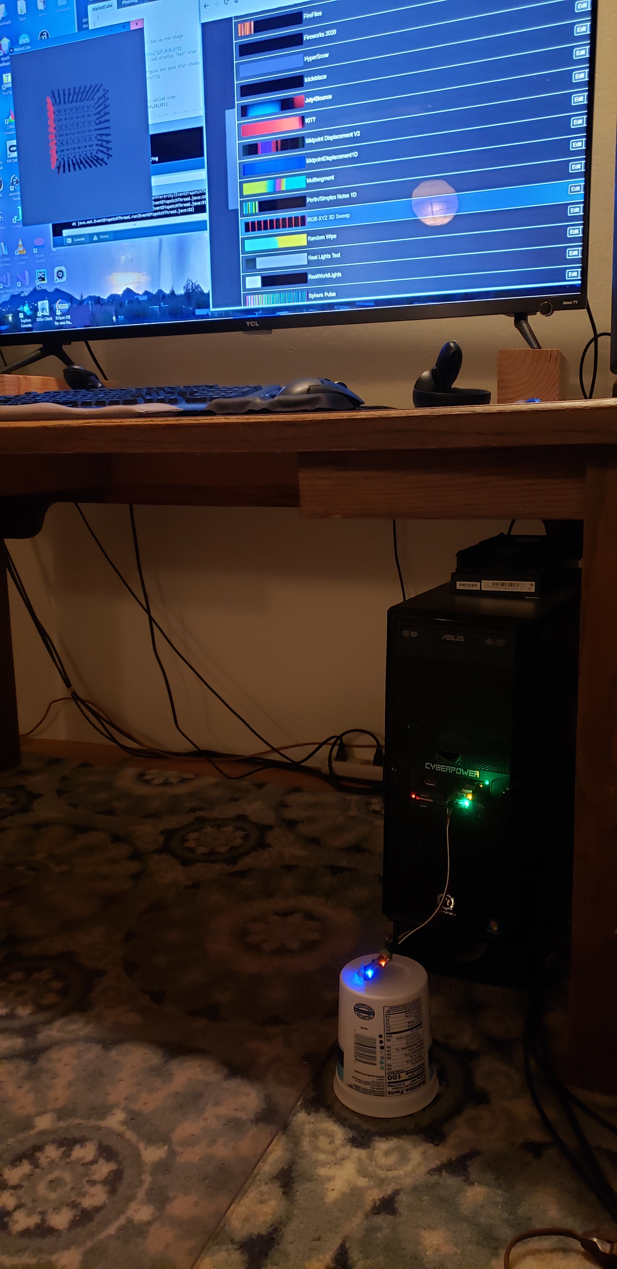
PixelTeleporter is a set of tools that let you send LED output from your Pixelblaze to your computer screen. It lets you write, test and debug patterns for LED displays of almost any 2D or 3D layout without having the actual LEDs available.
I’ve just updated PixelTeleporter to version 1.0.0. The major change is that it’s now an installable library for Processing. The new library format:
cuts down the amount of boilerplate code needed in your sketches
makes the examples available directly in the Processing IDE
includes a lot more documentation
provides a much better framework for future expansion.
You can check out the docs and download it from here:
Thanks! I really appreciate that, coming from you guys – kylarleds, I was just admiring the clean, efficient code in your latest sound reactive pattern, and wizard, this project really made me aware of the huge power of the pixel mapper concept.
I can’t think of another controller that can switch from an xyz volumetric cube pattern to projecting x,y coords as longitude and latitude on the surface of a sphere in only a few seconds. Just… excellent.
(Looking forward to bug reports & feature requests! That video, um, does show off the functionality pretty well. I’ve got to get a real camera stand one of these days though.)
This is an awesome project! How is the ESP8266 at keeping up with the data for 2048 pixels over WiFi? I read a while back that streaming pixels to the ESP8266 was asking for trouble, but that was to not from and it was anecdotal and years ago.
When you get to the point of receiving APA102 data, I have an ESP32 based project where I sunk a lot of work into receiving APA102 data at a high rate (not an easy task). I’ve been using the ESP32 to receive APA102 data over I2S using DMA and interrupts so it’s running “in the background” and can probably coexist with WiFi. My application doesn’t use WiFi, it receives APA102 data and refreshes it on a HUB75 matrix. It’s going to be used in an open hardware product, but I haven’t published details yet. LMK if this would help with your project and I can share details if you can hold off on publishing my circuit and code until I’m ready.
Thanks for your kind words. I’d love to see how you handled I2S and DMA, if
you don’t mind. Absolutely no problem holding off any kind of publication 'till you
say so. I’m still playing with the ESP8266 for the APA102 code, but if I can’t get
the performance up, ESP32 it will be. HUB75 – beautiful display!
That’s gotta be fun to work with.
For this initial version, emulating the Pixelblaze output expander board
means that I get a very orderly 2Mhz serial data stream. I was able to
use the UART to read and buffer data. It’s fast enough that the buffer
stays mostly empty, even during the datagram send window at the end of each frame.
On the output side, the ESP only sends data on request. This reduces CPU load
and net traffic and allows the client application to throttle according to its
needs.
By default, Processing 3 draws at 60 fps. Even with 2K RGB pixels this isn’t
a ton of data going across the net. The ESP8266 is easily able to keep up the
pace and since most monitors still refresh at 60Hz, it’s ideal for this purpose.
Faster rates are workable. I’m currently experimenting with rendering POV effects
at 120+fps, with a few hundred pixels, and I haven’t yet caused a meltdown. Now
that the basics are working, there are many interesting things to try!
My project for the PixelBlaze was an LED portal for the Colorado burning man festival (A mini version of the huge one in Nevada) which I never finished due to having COVID, and then they cancelled the festival for this year, so I am working on building it for next years festival…It is 8 loops 2 feet apart with 64 LEDs with ping pong balls glued to them on each loop and a walkway at the bottom. Its 8 feet tall so people can walk through it. I had planned on building a mini version of it to work on patterns but now I won’t have to thanks to Jons PixelTeleporter application. Thanks Jon for that! I modified the cylinder rendering program so that it emulates the portal I will build, with the walkway at the bottom of it. Attached a GIF of the rendering…but that is my project for the next year to build this thing, and hopefully the festival goes on next year and I get to display it. For now at least I have a way to simulate it to work on patterns and I am grateful to Jon for that.
Thanks for sharing this! Glad you could use my code – that’s exactly the kind of project I was thinking of when I wrote it. (Plus, you reminded me that it would be handy for the ring generator to have a stop angle - it’s updated in the repository now. )
And here’s hoping 2021 is way more normal and you get to take your tunnel to the festival next year!
Just updated to add the ability to import and export Pixelblaze pixel mapper JSON maps (and fix a couple of minor bugs.) This feature lets you create a displayable object direcly from pixel mapper output.
See the new MapIO example in the repository for details.
There are differences in a couple of libraries, so the ESP8266 code almost certainly won’t work as-is on an ESP32. ESP32 support is on my list, along with Raspberry Pi and a few other things. It’s a week or so out at this point. (I’ve been focused on getting the generic APA 102 protocol reader going at a reasonably high speed. It’s been one of those interesting problems. Even if it never works the way I want on the 8266, I’ve learned enough to make it worthwhile.)
Just updated the core components. See the first message in this thread for more detail. We’re a real Processing library now!
Raspberry Pi support, and FTDI board interfaces for Linux & Windows are next on the todo list. Should be along shortly. (The APA102 reader is stalled at a snail-like 500Khz on ESP8266 – think I’m just going to move on to ESP32 for that one.)
Update to PixelTeleporter v1.1.0 is now up on GitHub. Includes Raspberry Pi serial support, and Linux and Windows support with an FTDI USB->Serial adapter. The best thing about this new release is that, with an FTDI board, you can now hook your Pixelblaze up to the same computer you’re using for the Processing scripts. Details on everything new in the various README files in the repository.
Of course, wired and wireless networks are supported, as are multiple LAN adapters on the server machine. (The server also supports sending Pixelblaze data to multiple clients, and other future oriented features – I’ve got a virtual LED-wiring-over-ethernet experiment on the roadmap.)
So now we don’t have to connect the PelexTeleporter(esp8266) to the PB as an expander? I’m sorry but my brain is really not getting how these are all connected and setup. Anyone make a tutorial yet?
When you say FTDI to USB are you meaning this http://amazon.com/Adapter-Serial-Converter-Development-Projects/dp/B075N82CDL ? I can’t make it out in your pic what it is. Have a link to what you are using?
My fault for not making the architecture more clear. I’ve been living with this idea for long enough that I kinda lose track of what might not be immediately obvious…
PixelTeleporter comes in two pieces
a Server, which hooks to Pixelblaze and sends data to a computer.
a Client - the PixelTeleporter Processing library, which receives and displays the data.
Prior versions had only the ESP8266 server, because that’s the first one I wrote and I used it to test everything else. I’ve finally gotten around to writing servers for other platforms: Pi, Linux and Windows. It doesn’t change how things work. It just gives you more choices so you can use the hardware setup that’s handiest for you.
The ESP8266 and Raspberry Pi servers require no additional hardware to talk to Pixelblaze. The Linux and Windows servers require an FTDI or compatible USB->Serial adapter.
The “connect to the same PC you use for Processing” feature falls out naturally from the way the network stack works. The client and server will always think they’re sending data across the net.
But if you run the server on a machine, and give Processing on that same machine the localhost address (127.0.0.1), it will grab the data quickly and efficiently from internal buffers, without anything at all going over the actual network.
There are fairly detailed setup instructions for each server in the README.md files in the individual subdirectories in the servers directory of the repository. And I’ll do my best to answer any questions that come up.
It really is an amazingly cool idea and implementation. I’d say “May I ask one more question” but that would probably be a lie. I ordered the adapter. I have never used an adapter like that can you explain the connection between the PB and the adapter? Is it…
Adapter switched to 5v? or 3v?
Adapter(RX)-------------> PB(TX)
Adapter(TX)-------------> PB(RX)
Adapter(GND)----------> PB(GND)
Adapter(Vcc)------------> PB(3V) or Maybe the 5v pad on the back of the PB?
The adapter works with USB 2 or later. Windows 10 will automatically install the FTDI drivers when you plug the adapter in, Linux comes with them installed. For older Windows and others, the drivers can be downloaded from FTDI’s web site.
Oh wow, I was off on my thinking. So it’s the led output on the PB to the adapter. Was that the same when the server was the ESP8266? I thought we soldered the header onto the PB and used those pins to connect to the ESP8266…
I think that is also my mistake in thinking the 8 port expansion board got connected to the header pins on the PB and not to the GND/DAT/CLK/VIN led output from the PB.
I hope I am right that the header pins on the PB are for the sensor board.
WOW was I off in my thinking. I wonder if I am the only one thinking that? Perhaps I missed it in the docs. I probably went wrong when I started thinking that the PB LED outputs are ONLY for LEDs which seems is totally NOT the case.