Can I power the strips from a 12v power supply and independently power the Pixelblaze from USB?
(This isn’t specifically covered in either the QuickStart or the Hardware Setup documents. It only mentions that “If you are using 12V LEDs, a separate 5V supply is needed for Pixelblaze.”, but doesn’t specifically say that a USB supply will work or not.)
You may have data line issues, due to different ground levels. May.
Remember the PB generates the data line, even if the LEDs are powered by other means (in this case, 12v instead of 5v)
As confirmed by a quick google:
… the LEDs chips used in 12v strips (such as the WS2815) each contain an internal voltage regulator to provide a 5v supply to the chip’s logic.
I would assume that I’d have to hook the ground connection from the strip to the PixelBlaze and that would be the common ground between the two.
That is effectively the same wiring as using an external 5V power supply with the 12V strips, right?
The internal implementation details of the strip is irrelevant. If I were to use power injection for a series of 5v strips – a separate supply for strip vs. PB – I’d still have a common ground.
The question here is can I replace separate 5V supply with the USB supply?
Or, I suppose, does the USB power share a common ground with the strip?
Yes, a USB power supply works the same as any other power supply. Negative/gnd is connected internally from the USB ground to the terminal ground so you don’t have to worry too much, just don’t connect +12v to the PB.
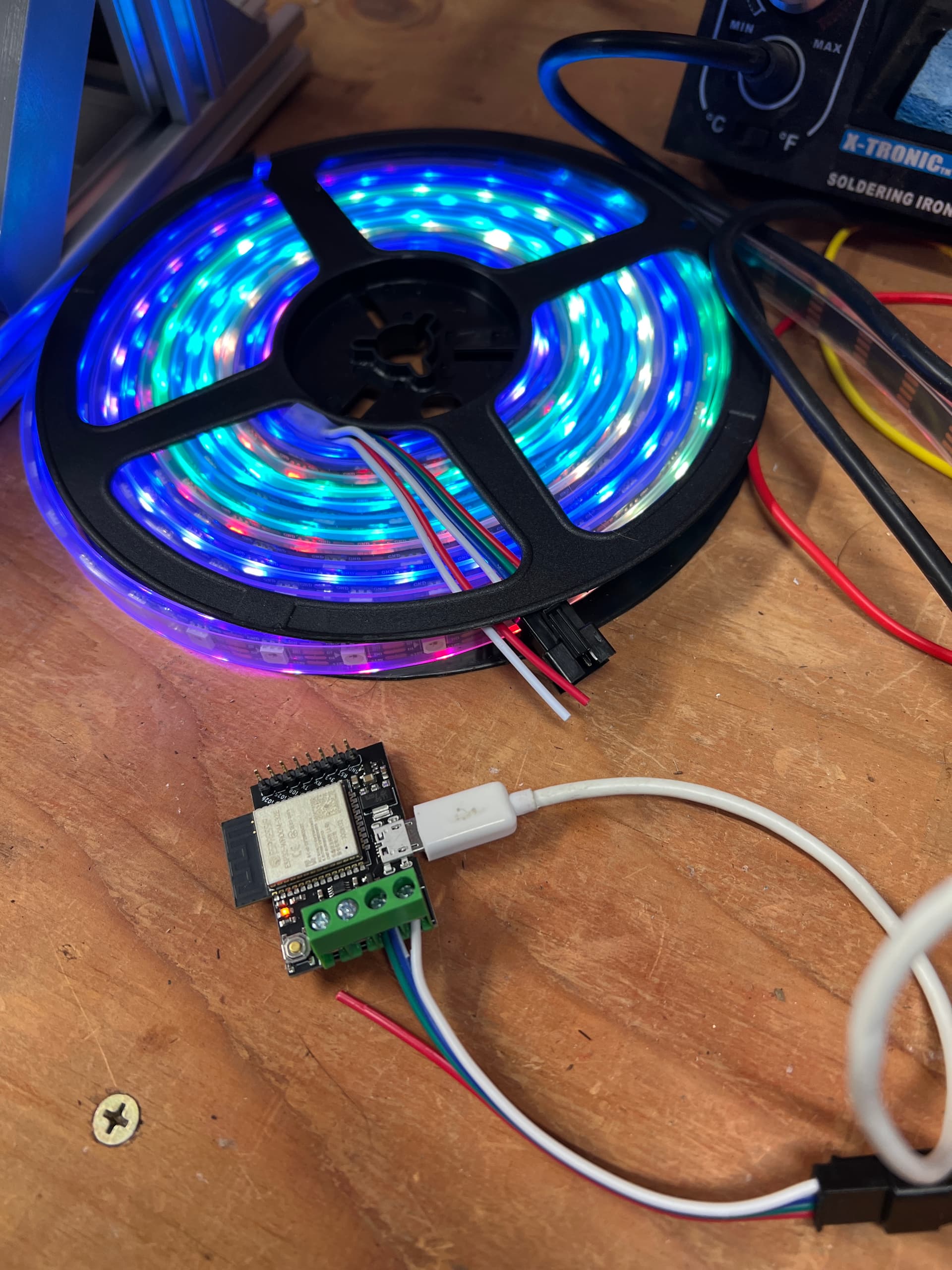
And, btw, USB Brick + 12v externally supplied WS2815 w/only ground connected works perfectly!
(Off camera to the right is an ancient bench supply feeding 12v to the power injector connections of the strip. If you look closely at the picture, VCC is not connected from the strip to the PB. Note that I connected both data pins together to the DATA pin on the PB as this is a WS2815 w/redundant data pins).
Could you make up a small step-down board from an AMS1117 or L7805 voltage regulator and maybe a filtering capacitor? If you’re not using the header pins, you could stick a female header on the underside of a piece of perfboard that isn’t electrically connected to anything and size it to bridge over to the top of the screw terminal block for mechanical stability. Then you could use the same 12V supply for both. N.B., I am not an EE some there may be more to it than I think, but it seems perfectly cromulent to me.
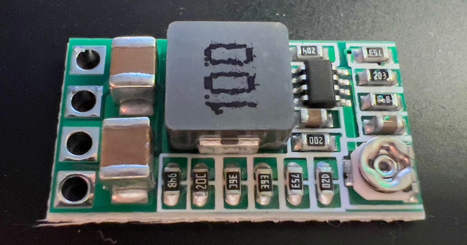
No need to make a board. Buck converters are cheap from your typical electronics mail order place. I picked up one that’ll happily do 12v to either 5v or 3.3v and will use that as the supply. Alternatively, a car USB wart would work, too, if I had one handy.
Some are adjustable. On a few, you can cut a trace on the back of the converter and then solder a jumper in another spot to select specific voltages!
Yes, always connect GND. The converter’s GND, 12V power GND, and Pixelblaze’s GND should all be connected via some path. All current travels in a loop (circuit), and you generally want these paths to only be as long as necessary, so the converter’s GND and output would be connected to PB, and the converters GND and input would be connected to the 12V power supply.
Yes, the 5V only needs to be connected to the PB, unless you need 5V for some other reason, but you definitely do NOT want to connect the 12V and 5V positives together.
Generally you only need to count the distance to the first pixel. Most addressable LEDs regenerate the signal from one LED to the next, so you don’t need to total up the entire strip length. But, long distances to the first pixel can cause problems.
For long distance runs like this, you could use a differential transceiver, like an RS422/RS485 or insert a few single pixels along the way to make each hop relatively short, every 10-15ft or so. You can wrap those up so they aren’t visible, but will still regenerate the data signal. Sometimes called ghost pixels.
Thank you very much, this is answering my questions.
By DISTANCE to the first pixel (or in between 2 LED strips i assume), what do you mean ? 1M ? 10M ?
The idea is to have 3-4 installations of a 1-2M strip, separated by a cable to connect all of them together. I expect 2-3M spacing easily. Is the issue basically voltage drop in the data line, and could be mitigated by using a thick cable ?
EDIT: woops sorry i didn’t see you advised every 10-15ft. Thank you !