Power supply and wiring advice needed

I’m working on my first pixel blaze installation and I could use a recommendations on which power supply to buy (or how to choose one), which wire to buy to span the ~8ft gap between strips, and about how to wire my power injection.

The installation comprises of 8 columns, about 8 feet apart from one another. LED lights wrap around a wooden post at the center of each column. Fabric stretchs from top to bottom of each column diffusing the light.

The installation will use about 720 12v WS2815 LEDs divided up between the 8 columns (90 LEDs per column).

This will be installed on the playa at burning man, and wires will be buried between columns to keep people from tripping on them.

I have chosen wire and connectors online (shown in diagram). Are these sufficient for weather proofing and for carrying a signal the entire length of the installation?

How do I find the right power supply?

How should I approach power injection over this distance and with 720 12v LEDs?

Thanks for your help :pray:


I’m not a pro so take it with a grain of salt but you could consider using a 48V (or more ?) power supply to reduce intensity in the cables, and a small DC-DC 48V to 12V step down circuit in each column (it’s pretty cheap if you buy it on Aliexpress, found some at less than 10 USD). That way each column is regulated at 12V so luminosity will be the same despite being able to put your columns in parallel over 1 cable (much more simple).

You could also litterally send AC current to each column and convert to 12V on the spot, but I’m not sure how the data line between the columns will react being burried next to an AC wire. It’s also less safe, particularly in regards to below.

For your connectors, i’ve used these under heavy moonsoon rain without any issues in a tree, but I wouldn’t assume (unless specified on yours) they are “waterproof”, which is probably what you need to be buried in the playa in case of heavy rain/mud like last year. If your connectors are above the ground though, that seems fine enough to me to run the cable, but again i’m not an electrician.

Also: think of putting fuses. One wrong connection/short circuit and each of your columns will be fried.

1 Like

For the power distribution I agree with @hololit to use local downtown converts for each pole. in this case GND must be common but 12V must not be connected together (must be individual per pole).
Assuming all strips will be serially connected and driven by single PB signal integrity could/will be comprised because of very long 16ft (8ft between poles + 8ft from top to bottom) run between strips. Comprised signal integrity may/will lead to a bad random flickering. You definitely will need a twisted pair wiring for signal line (GND + Signal in each pair). Twisted pair wires could be extracted by slicing Ethernet cable (it has 4 twisted pairs).

To add about long data lines. Usually you can run up to 5M without any issues without amplifying the data (which is then re-amplified in each column before going to the next one).
To avoid any issue you could install also a differential signal communication.

But have a look at this:

I believe if you do some tests you might be able to avoid the hassle without taking a lot of risk.

This [quinled] person has a very little understanding what he is talking about.
The main reason for the bad/compromised signal integrity is a “reflections” at each end of the cable/wire. The “reflections” is not mentioned at all.
In short:

  • The impendence of the used wires must match the impendence of the driver;
  • Each single-ended transmission line must have a return wire. That is why you should used a twisted pair (GND-Signal). Differential signaling is a bit different story but far more better for the long runs;

LED control signal is a 40-60 PWM which is naturally very well DC-balanced. Because of this signal nature it is somewhat forgiven for the bad wiring but it does not mean it is OK to follow this path.

Hi @Nfiniteset ,
Welcome! Your project sounds awesome!

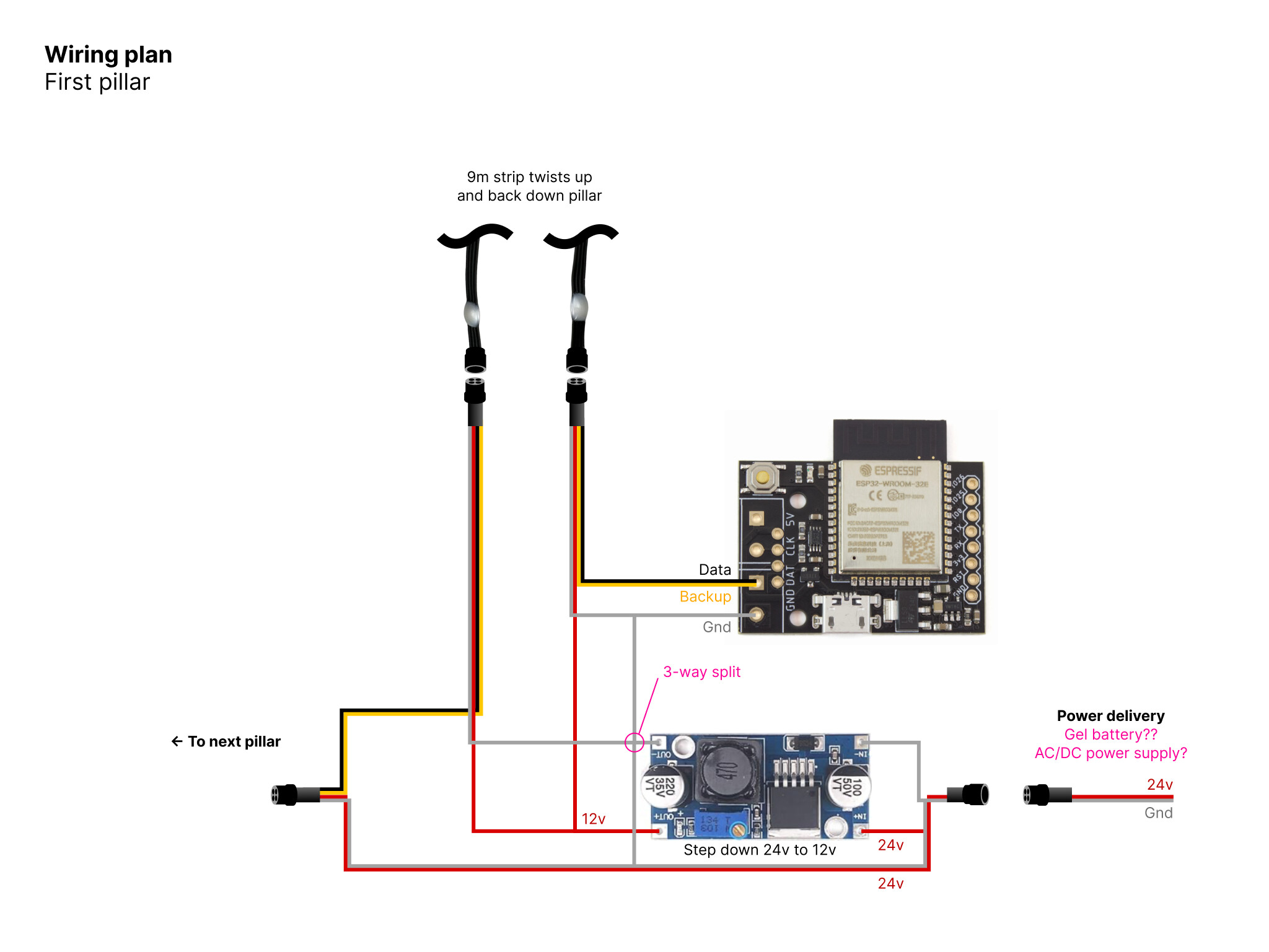
For power, have you considered solar + batteries for power? You can run WS2815 right off a 12V battery system. I’ve had good luck with both 12V and 24V systems using fairly affordable Renology chargers and panels, along with deep cycle gel batteries.

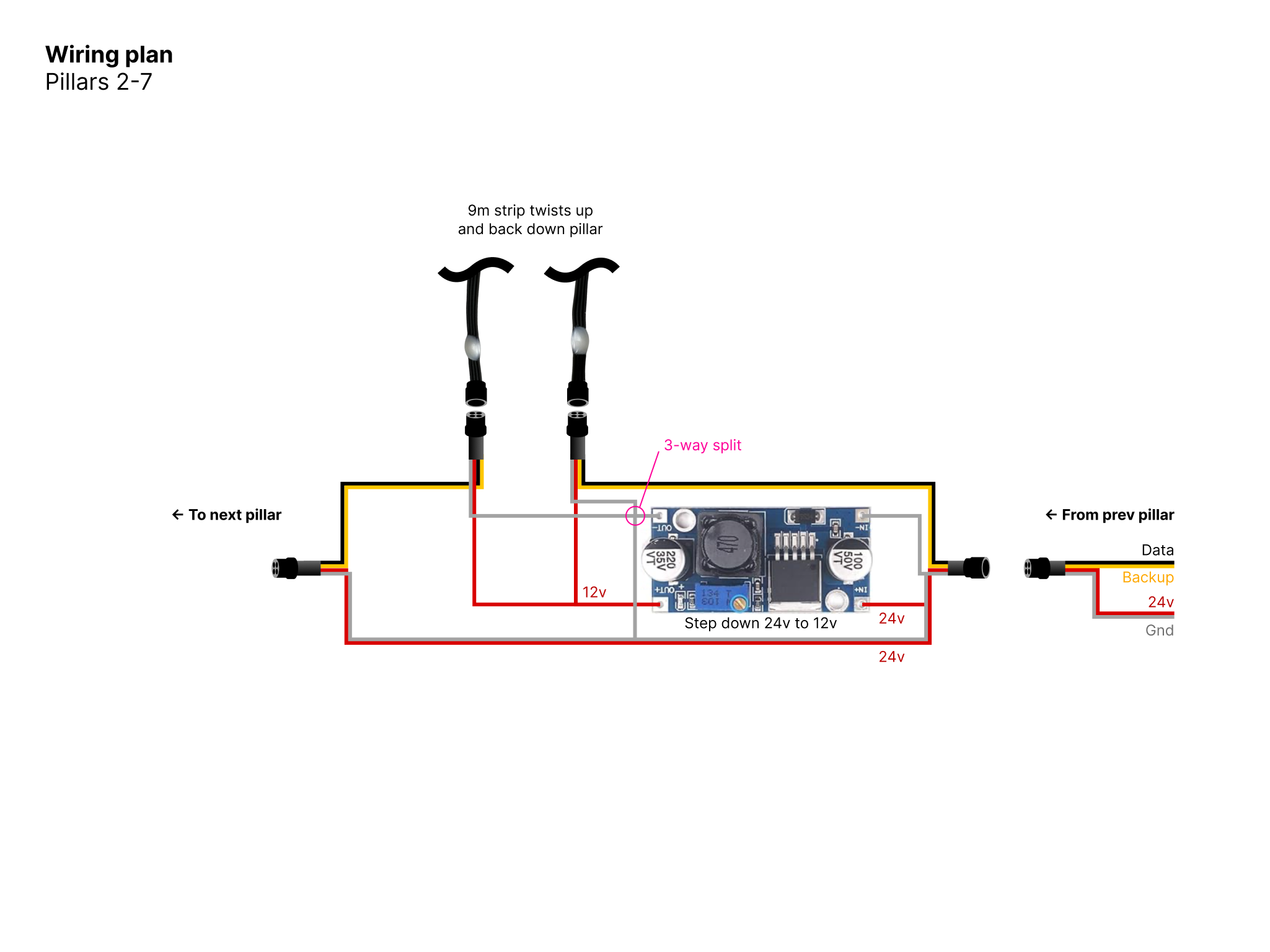
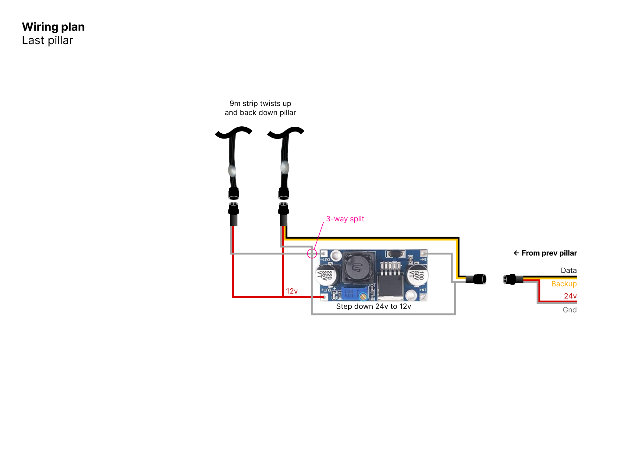
Adding on to what others have recommended, a 24V solar system with buck converters in each pole would probably improve your power efficiency (over 12V) since you end up losing less power in the wires.

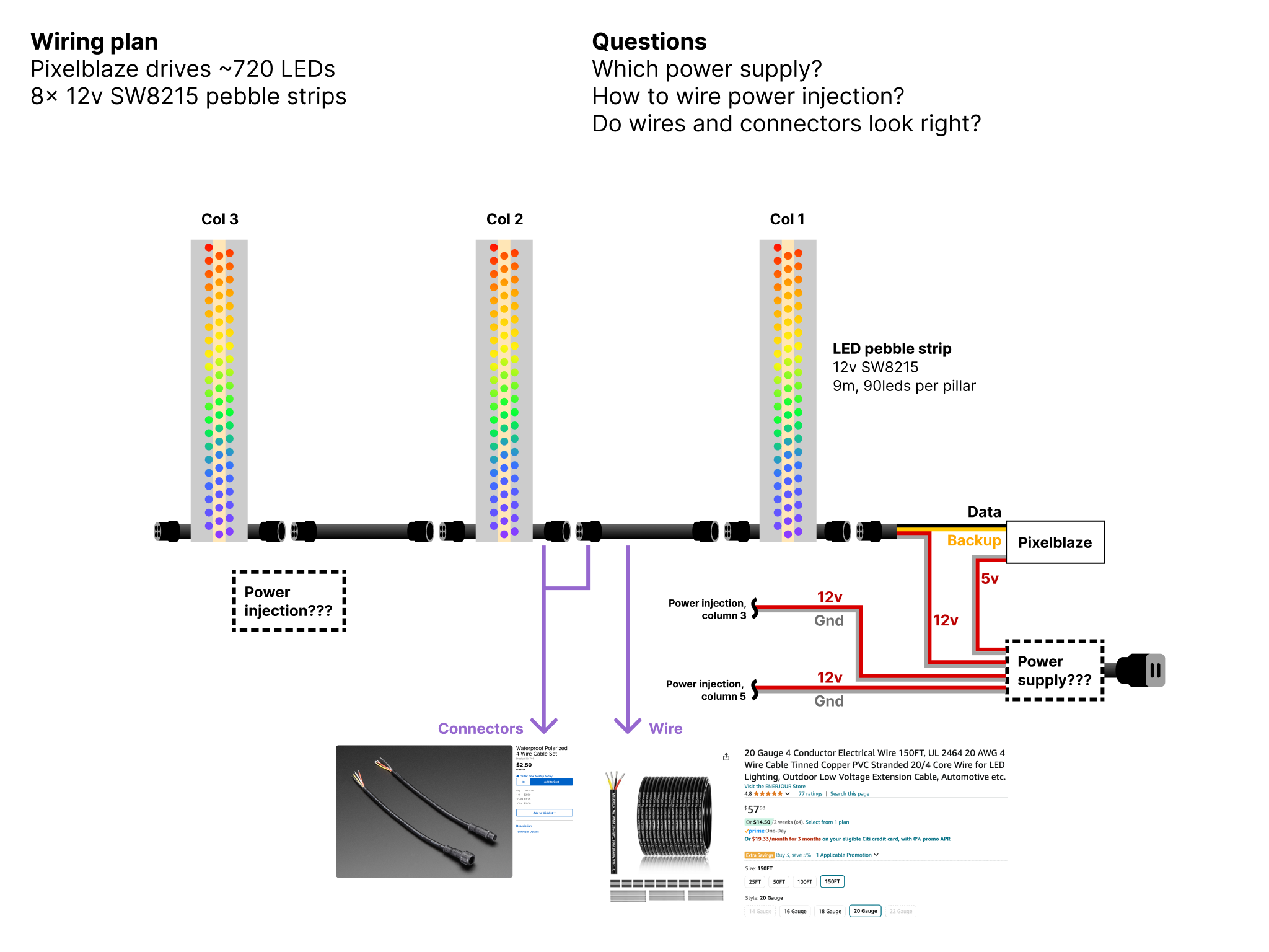
I would power your LEDs from both ends (run power to the top of the pole too, both - and +) for two reasons :

  1. This improves the output data signal for sending over a longer distance. Any voltage difference between the output and input LEDs only makes data signal issues worse, so its best to make that the same voltage by wiring power to both ends.
  2. That helps with voltage drop along the strip, and would let you drop the working voltage near the minimum, improving efficiency.

WS2815 draw around 13ma on max brightness regardless of color, so figure on 1.17A per pole. They will also work just as well at 10V, so if you are converting down from 24V+ you can eek out even more efficiency by tuning your buck converter to output 10V or so.

Something like these should work OK:

The key trick with these is that you want to adjust the voltage before connecting to LEDs, you don’t want to accidentally over-voltage your LEDs. Connect a multi meter to the output, power the input, and adjust the small blue pot with a tiny screwdriver. These will get hot with high currents, but 1A should be OK.

These kind of converters are not great for Pixelblaze itself, for that I would recommend a mini-buck for 12V systems.

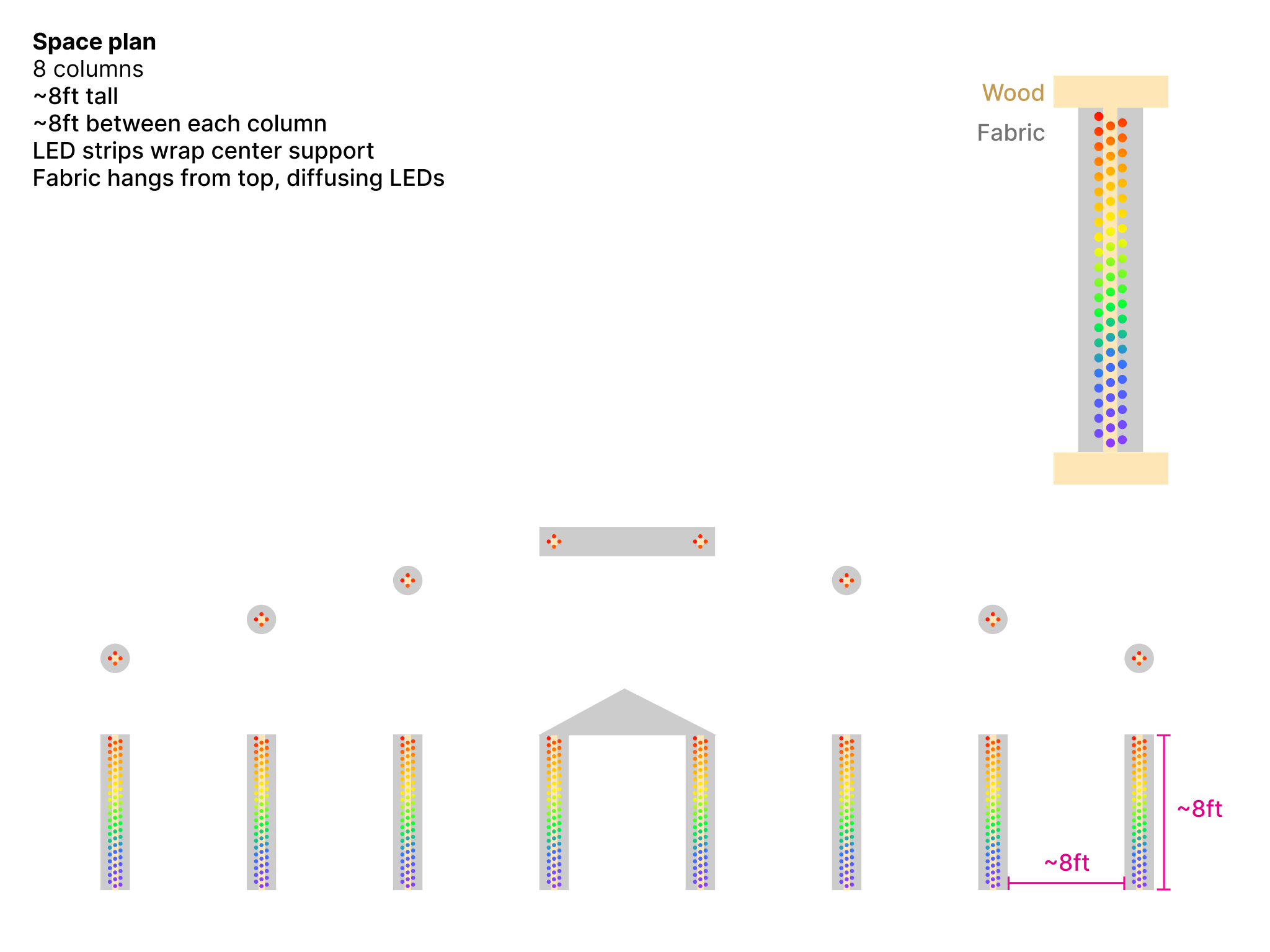
For data signal integrity, your data lines have 16 ft between the top of the pole and the next pole (assuming you wired them bottom up, but it would be 16 ft either way). Thats marginal. It would probably work, but there’s a chance it would flicker, which is the WORST, so I would design to avoid that if possible.

If you can drop that down to 8ft, you should have no problems. One way to do that is to wire from the top to a single LED in the base right before the output. This LED would act like a repeater and “reset” the distance. It would still take a pixel worth of data though, for most things that wouldn’t impact animations in any great way. If it was visually distracting, you could hide it.

Another way to do that would be to change how you wrap the pole. Use half to run upward, and the other half to run downward. That would be a little more complex to pixel map, but would be another way to get the output and input at the base to minimize distance and require no extra LEDs.

Thanks for all the helpful info, folks!

Here’s a revised diagram showing my understanding of your collective suggestions. Please validate that I understood you correctly. I have a few more questions as well. This is my first electronics project, so be specific if possible :pray:

Powering the Pixelblaze
@wizard , you said the step-down boards aren’t great for PB, and to use a mini-buck. But the standard PB should be able to handle 12v, right? Does the pay I power the PB look safe?

What to do about twisted pair
Are you suggesting I use ethernet cable to carry the data line between pillars, @Vitaliy? And carry power in a separate wire?

What to do about impedance
How do I apply the advice about impedance @Vitaliy? Does the PB set the impedance standard or does the step-down? This impacts the type of wire I’m meant to use, right? Please elaborate.

What about fuses?
What specifications of fuse should I have, and where do they go in the diagram? I’m also wondering if a fuse blows on the playa, can I replace it without re-wiring anything? I need to minimize fussy work on the playa as much as possible.


You can use a standard Ethernet (CAT6,6,7) Cable for both Power and Signal.
On each end you can use something like this:

Each cable has 4 twisted pair (8 conductors). Each individual wire is capable to carry 1A of current or even more (need to check latest spec).
Say use first pair for Signal and the other 3 pairs for power delivery. You can use 3 conductors for VCC and 3 conductors for GND. This way total current could be up to 3-4A. @wizard estimated max current around 1.2A @ 12V. If you use 35V power source the current will drop to approximately 0.45A @ 35V totaling to 3.6A for the last segment in a chain. So, single Ether cable should do the job for carrying Signal and Power for each poll.

Pixelblaze has a 100 ohm serial resistor for the Data and CLK signals. This should be OK but only for the first segment between Pixelblaze and very first poll. All other polls will be drive only by the very weak output from the last LED in a segment. The LED output was not design to drive long cables but you can try. Using twisted pair for Signal definitely will help. However if it were me I will use a strong buffer (cannot recommend any from the top of my head) after last LED for driving next segment in a chain.

1 Like