Problem using every GPIO

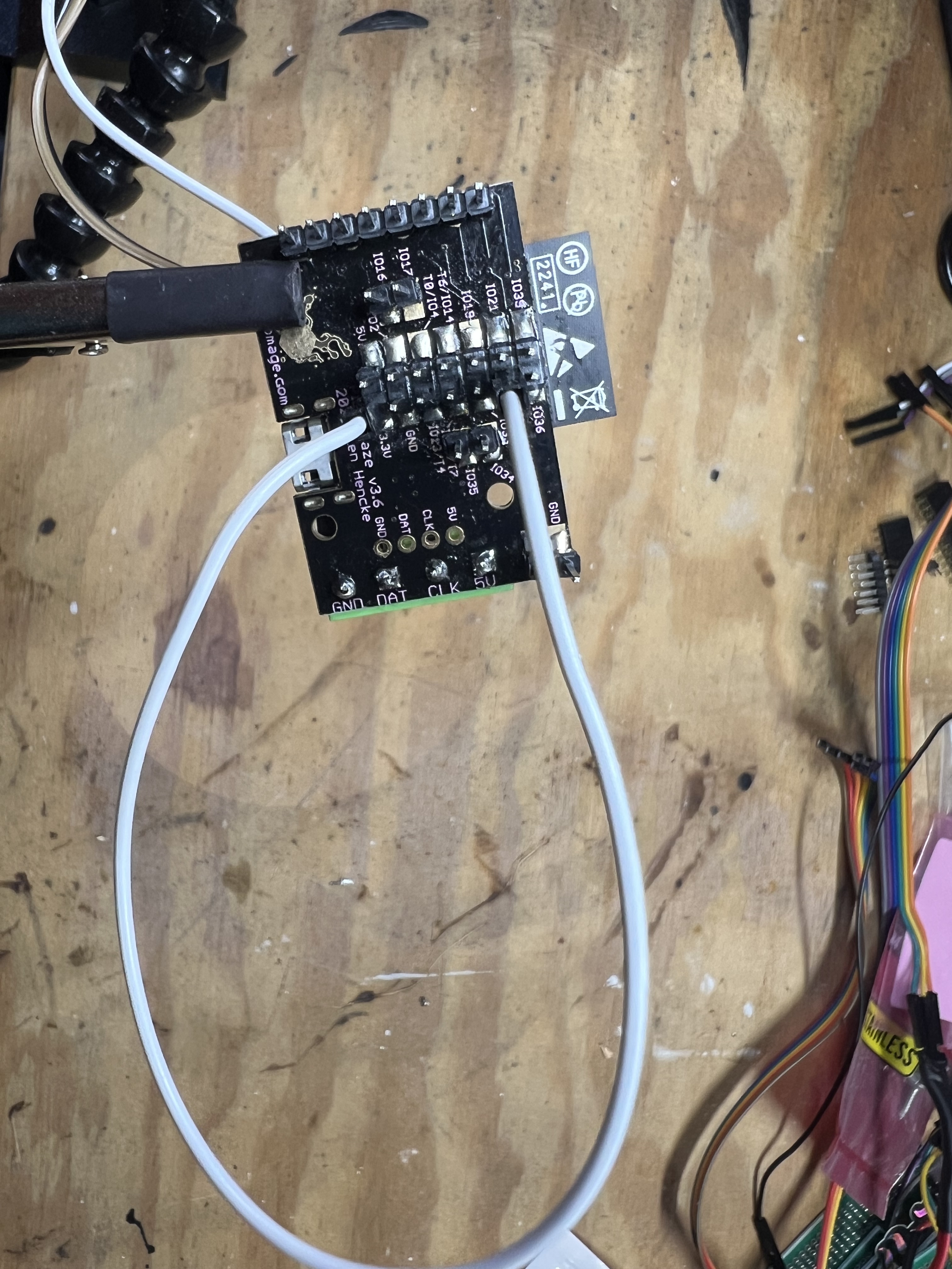
Hi, I am working on a project to use many GPIO ports to control LEDs. I basically rigged up a box with buttons, switches and knobs wired to every GPIO pin. I started with a V3 standard and noticed some of my pins were crossing, meaning I would trigger one pin, but 2 or 3 would pick up a signal. I assumed it was my fault, so I desoldered, soldered, pulled my hair out, desoldered again, again, and finally I damaged the board so I threw in the towel and bought a new V3 standard and started over. This time, I took every precaution and soldered a clean pin header to the board. To my surprise, the exact same pins are crossing. I think I found a bug. Most pins work great, but these seem to cross:

IO21 triggers 21 and 39, but 39 does not trigger 21
IO22 triggers 22, 33, 34, and 36
IO27 triggers 27, 34 and 35
IO33 triggers 33, 22, 34 and 36
IO35 tiggers 35 and 34

The weird thing is that some pins like 36 and 34 work just fine, but they get triggered by several other pins too. This makes me think that it can’t be bad soldering/wiring, like if I had bridged the pads somehow. If it were, should triggering IO35 or IO34 should trigger both. But, if I send 3.3v to IO34, only 34 gets triggered, not IO35. If I trigger IO35, both 34 and 35 get triggered.

I hope that makes sense. Maybe there is an obvious reason for this, but I figured I’d ask, and/or let you know in case it’s fixable.

Also, the GPIO documentation here says there is an IO12. I think that’s a typo, it should be IO22

Hi @MrMatty ,
Oh no! Thats frustrating.

Can you upload an example pattern that shows this? How do you have these wired up to the buttons/switches?

One thing I would look for is that your inputs have pull ups or pull downs.

Not all GPIO pins support this built-in. GPIO 34 and up are input only pins and do not have the ability to enable a pull up/down resistor internally on the ESP32 (they can’t drive a signal on those pins, even weakly). An external resistor would be necessary if you are only controlling one of the states, e.g. with a button. They should be fine without it if you are driving with an active digital signal that drives both high and low.

GPIO pins if left floating can end up reading random values, or might be picking up nearby signals. I suspect that’s why you are seeing activity on the 34 and up pins, but doesn’t explain what you see with GPIO 33 if you configured it with a pull up/down.

Can I swap out your cooked V3?

Thanks for noticing this! I’ve fixed this and added notes about the IO34-IO39 not supporting INPUT_PULLUP and INPUT_PULLDOWN. It’ll be deployed soon!

No worries. To be honest, I kind of enjoy troubleshooting, but wasn’t sure if it was me or not until today. The fried v3 is in rough shape now, but I won’t turn down a replacement if you’re offering.

I soldered a pin header to the pads and I’m connecting the GPIO pins directly to the 3.3v pin with a wire so that I can rule out the rest of my wiring.

There is no specific program where I see it happen. I can see the signal come up in the vars watch. You can see all the values change as you send a current to the pins.

I am currently using INPUT_PULLUP or INPUT_PULLDOWN. Same result.

This topic was automatically closed 120 days after the last reply. New replies are no longer allowed.