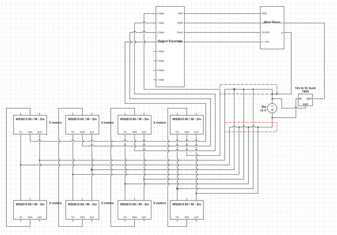
Brief description Im making 8 x 2m led tubes out of this 360 profile ( for simplicity im only showing 4 here / psu rated for 4 ). There will be 2m leds of leds on each sides of the heatsink. Power will be connected at the bottom for each side to avoid voltage drop. Then at the top the data line will make all the leds in one tube one ‘channel’.
Wondering
(1) Main thing im not sure about is the common ground. Im connecting the ground of the Pixel Blaze to the ground of the 12v supply. I think then all the ground in the system is common and i only need to connect the data lines from the output expander. Is this correct and will it work ? ( I have never done something like this with multiple voltages so know little about ground ! )
(2) Anything else look like its not going to work ?
All wiring is 18awg apart from :
- The 5v wiring and the connections between the PB and Output expander
- Where the dotted lines are there are bus bars distrubting power to each tube these are connected to the PSU with 12awg as load is to much for 18awg
Thanks thanks thanks. Im making these for my wedding 1st October so any help for a newbie would be amazing ![]()
