Sensor board serial protocol

I’m want to be able to use a rotary encoder to control brightness and change patterns. I figure I can do that using an extra microcontroller to read the encoder, then talk to the PB via serial as if it were a sensor board.

So, would you be willing to share what the serial protocol looks like? Or will I need to figure that out the hard way?

It’s open source! It’s described here:

You can also reference or even reuse the source.

Looks like the WRITEOUT stuff here might be the implementation of the protocol:

1 Like

Oh no way. Awesome, thanks!

There’s also an arduino library to parse it, might be useful as well for code bits or to help debug and verify your output.

1 Like

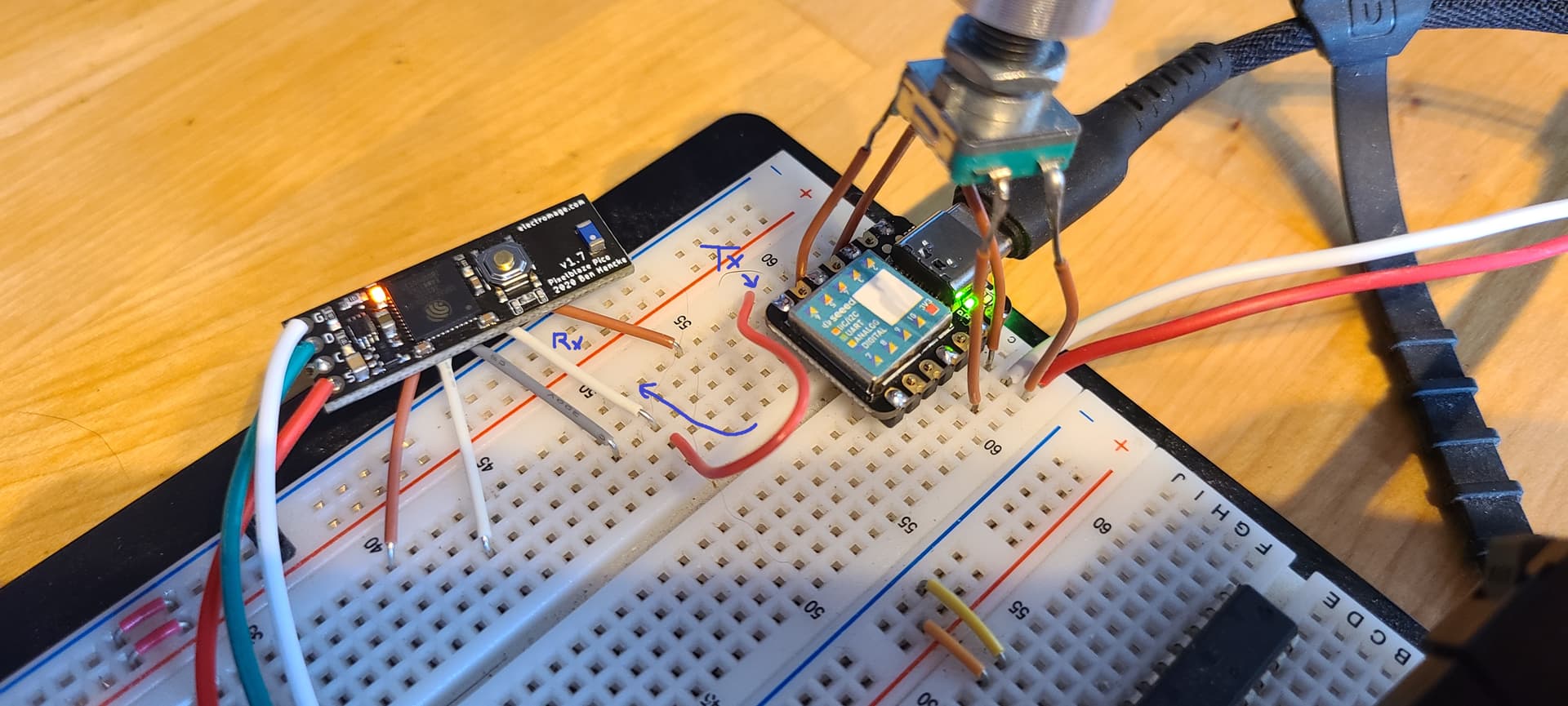
I’m doing a similar thing, I use an esp32 to parse the sensor stream, then add multiple analog input data to it.

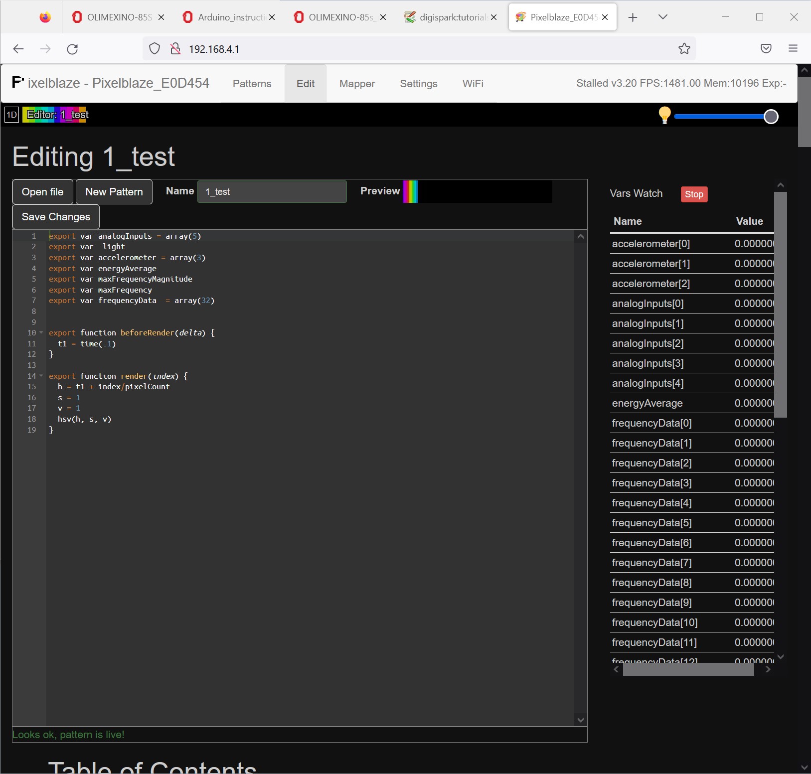
Here’s some code to read the stream:

#define START_BYTES 5
#define LENGTH      98

const byte startMarker[START_BYTES] = {'S', 'B', '1', '.', '0'};

byte receivedBytes[LENGTH];
uint8_t idx = 0;

boolean processData = false;
boolean started     = false;


void SensorBoard()  //  SENSOR BOARD READ ROUTINE
{
  while (Serial1.available() > 0)                           // Something to receive?
  {
    receivedBytes[idx++] = Serial1.read();                  // Read next byte into array

    if (! started)                                         // Are we still trying to find the start marker?
    {
      if (receivedBytes[idx - 1] != startMarker[idx - 1])  // Check if the byte received matches expected.
        idx = 0;                                           // If not, start over.

      if (idx == START_BYTES)                              // Have we got all 6 bytes?
        started = true;                                    // Then we're started, so will read reset of data.
    }
    else                                                   // We're started.
    {
      if (idx == LENGTH)                                   // Read to the end?
        processData = true;                                // Set the flag so the data gets processed.
    }
  }


  if (processData)                                         // Flag set?
  {
    for (uint8_t x = 0; x < LENGTH; x++)                   // Loop through the array.
    {
        freq[0] = receivedBytes[6];  // If you want to keep some of the sensor board data- i.e. audio, add it here
        freq[1] = receivedBytes[7];
    }
    started = false;                                       // Start looking for the start marker again.
    processData = false;                                   // Clear the processing flag.
    idx = 0;                                               // Reset the array index to start over.
  }
}

Here’s how I write back to PB:

byte header[] = {0x53, 0x42, 0x31, 0x2E, 0x30, 0x00};  //HEADER   SB1.0

byte freq[] =     {0x00, 0x00, 0x00, 0x00, 0x00, 0x00, 0x00, 0x00, 0x00, 0x00, 0x00, 0x00,     // FREQUENCY 1/6
                   0x00, 0x00, 0x00, 0x00, 0x00, 0x00, 0x00, 0x00, 0x00, 0x00, 0x00, 0x00,    // FREQUENCY 2/6
                   0x00, 0x00, 0x00, 0x00, 0x00, 0x00, 0x00, 0x00, 0x00, 0x00, 0x00, 0x00,    // FREQUENCY 3/6
                   0x00, 0x00, 0x00, 0x00, 0x00, 0x00, 0x00, 0x00, 0x00, 0x00, 0x00, 0x00,    // FREQUENCY 4/6
                   0x00, 0x00, 0x00, 0x00, 0x00, 0x00, 0x00, 0x00, 0x00, 0x00, 0x00, 0x00,    // FREQUENCY 5/6
                   0x00, 0x00, 0x00, 0x00
                  };                                                    // FREQUENCY 6/6

byte audio[] =    {0x00, 0x00, 0x00, 0x00, 0x00, 0x00};    // AUDIO ENERGY

byte acc[] =      {0x00, 0x00, 0x00, 0x00, 0x00, 0x00};    //ACCELEROMETER

byte light[] =    {0x00, 0x00};    // LIGHT SENSOR

byte analog[] =  {0x00, 0x00, 0x00, 0x00, 0x00, 0x00, 0x00, 0x00, 0x00, 0x00};    //ANALOG INPUTS

byte end[] =      {0x45, 0x4E, 0x44, 0x00};    // END


int SerialPeriod = 40;  // Serial1 Write interval
unsigned long SerialTime_now = 0;

void loop() {

Colour1A = (analogRead(27)) * 16;   // An example of sending analog data over to PB using some of the frequency bytes
    freq[0] = (Colour1A & 0xFF);
    freq[1] = ((Colour1A >> 8) & 0xFF);

    Colour1B = (analogRead(14)) * 16;
    freq[2] = (Colour1B & 0xFF);
    freq[3] = ((Colour1B >> 8) & 0xFF);

if ((unsigned long)(millis() - SerialTime_now) > SerialPeriod) {   //Send to PB every 40ms
    SerialTime_now = millis();

    Serial1.write(header, sizeof(header));
    Serial1.write(freq, sizeof(freq));
    Serial1.write(audio, sizeof(audio));
    Serial1.write(acc, sizeof(acc));
    Serial1.write(light, sizeof(light));
    Serial1.write(analog, sizeof(analog));
    Serial1.write(end, sizeof(end));

  }
1 Like

Perfect, that will help a lot! Thank you!

Ok so I got this microcontroller configured to read the rotary knob and spit our serial, but I can’t seem to get anything into the PB. I’m not sure where the message is lost between the mcu writing to serial and the watch variables on the PB interface.

Admittedly I have no previous experience communicating between devices via Serial. Do I need any sort of pullup/down resistor? I just connect Tx to Rx right?

Using Petrol’s example, I have my code configured to write out the header, then 0x77 for a bunch of sensor values for testing purposes, then the end header. I know the mcu is writing something out because it looks like this on the serial monitor:

Do I have the variable names wrong in the PB editor?
Will the watch variables not update if I don’t use them anywhere?
Do I have the serial configuration correct?
Any other troubleshooting strategies I could try? Another way to verify the PB is receiving serial comms?

My code (abbreviated):

byte freq[] =     {0x77, 0x00, 0x00, 0x00, 0x00, 0x00, 0x00, 0x00, 0x00, 0x00, 0x00, 0x00,     // FREQUENCY 1/6
                   0x00, 0x00, 0x00, 0x00, 0x00, 0x00, 0x00, 0x00, 0x00, 0x00, 0x00, 0x00,    // FREQUENCY 2/6
                   0x00, 0x00, 0x00, 0x00, 0x00, 0x00, 0x00, 0x00, 0x00, 0x00, 0x00, 0x00,    // FREQUENCY 3/6
                   0x00, 0x00, 0x00, 0x00, 0x00, 0x00, 0x00, 0x00, 0x00, 0x00, 0x00, 0x00,    // FREQUENCY 4/6
                   0x00, 0x00, 0x00, 0x00, 0x00, 0x00, 0x00, 0x00, 0x00, 0x00, 0x00, 0x00,    // FREQUENCY 5/6
                   0x00, 0x00, 0x00, 0x00
                  };                                                    // FREQUENCY 6/6
byte audio[] =    {0x77, 0x00, 0x00, 0x00, 0x00, 0x00};    // AUDIO ENERGY
byte acc[] =      {0x77, 0x00, 0x00, 0x00, 0x00, 0x00};    //ACCELEROMETER
byte light[] =    {0x77, 0x00};    // LIGHT SENSOR
byte analog[] =  {0x77, 0x77, 0x00, 0x00, 0x00, 0x00, 0x00, 0x00, 0x00, 0x00};    //ANALOG INPUTS
byte end[] =      {0x45, 0x4E, 0x44, 0x00};    // END

void setup() {
  Serial.begin(115200);
  pinMode(ENCODER_BTN, INPUT_PULLUP);
  encoder.write(0);
  attachInterrupt(digitalPinToInterrupt(ENCODER_BTN), debounceButton, CHANGE);
}

int oldPosition = 0;
void loop() {

  int newPosition = (encoder.read() >> 2);
  if(newPosition != encoder_value) {
    encoder_value = newPosition;

      Serial.write(header, sizeof(header));
      Serial.write(freq, sizeof(freq));
      Serial.write(audio, sizeof(audio));
      Serial.write(acc, sizeof(acc));
      Serial.write(light, sizeof(light));
      Serial.write(analog, sizeof(analog));
      Serial.write(end, sizeof(end));
  }
}

Check the structs referenced in the arduino library, and the sources, and the readme in the sensor board repo. Most values are 16 bits, not 8 bits. Some are signed, some are unsigned.

  1. Each frame starts with “SB1.0” including a null character (6 bytes).
  2. The frequency information follows, as 32 x 16-bit unsigned integers.
  3. Then is the audio energy average, max frequency magnitiude, max frequency Hz, all 3 as 16-bit unsigned ints.
  4. Next the accelerometer information as 3 x 16-bit signed integers.
  5. The data from the Light sensor is next, as a single 16-bit unsigned integer.
  6. Followed by the 5 x 16-bit analog inputs (12-bit resolution, shifted up to 16 bits)
  7. Finally “END” including a null character (4 bytes).

If you have another ESP laying around, you can use the sensor board arduino library to read and debug. If the library can’t read it, then Pixelblaze won’t be able to.

Personally, I would use the struct given in the library:

typedef struct {
//    char header[6]; // "SB1.0\0"
    uint16_t frequencyData[32];
    uint16_t energyAverage;
    uint16_t maxFrequencyMagnitude;
    uint16_t maxFrequency; //in hz
    int16_t accelerometer[3];
    uint16_t light;
    uint16_t analogInputs[5];
//    char end[4]; // "END\0"
} __attribute__((__packed__)) SB10Frame;

You could comment out the start and end char arrays, fill in all of the bits of the struct, then write out the whole thing in one Serial.write(&frame, sizeof(frame)).

These are available in the editor documentation, all the way at the bottom:

export var frequencyData
export var energyAverage
export var maxFrequencyMagnitude
export var maxFrequency
export var accelerometer
export var light
export var analogInputs

Yes, they update as long as the watcher is running. They don’t have to be consumed by code otherwise.

1 Like

Ok i’ll give the struct suggestion a shot… why do I comment out the start and char arrays? Those need to be written out, don’t they?

Still no luck…

Here’s what I have:

#include <Arduino.h>

struct {
    char header[6] = "SB1.0";
    uint16_t frequencyData[32];
    uint16_t energyAverage;
    uint16_t maxFrequencyMagnitude;
    uint16_t maxFrequency; //in hz
    int16_t accelerometer[3];
    uint16_t light;
    uint16_t analogInputs[5];
    char end[4] = "END";
} frame;

void setup() {
  Serial.begin(115200);
  
  frame.frequencyData[0] = 0x77;
  frame.energyAverage = 0x77;
  frame.maxFrequencyMagnitude = 0x77;
  frame.maxFrequency = 0x77;
  frame.accelerometer[0] = 0x77;
  frame.light = 0x77;
  frame.analogInputs[0] = 0x77;
}

long last_print_time = 0;
void loop() {  
  long now = millis();
  if(now - last_print_time > 40){
    last_print_time = now;
    Serial.write((uint8_t *)&frame, sizeof(frame));
  }
}

I tried it with and without the headers commented… still confused about that…

I had to cast the struct pointer as uint8_t pointer, otherwise the compiler complained about there not being an override for the argument types.

I think I have another esp32 dev board lying around, but that sounds like big ol’ adventure to get that set up to where I can learn anything from it… did I miss anything else?

The __attribute__((__packed__)) part is important. Otherwise the C compiler may pad the fields of the struct to make memory access faster. The total size of the data transmission should be 98 bytes.

Sorry, I meant uncomment. The library code comments those out so that you could see what a full frame would look like, while the code handles the header and end bit separately and doesn’t need them.

Ok I’ve added the packed attribute back in and verified the message is 98 bytes. Still not receiving anything. I’ll see if I can find a sensor board lying around to verify the PB would respond to that.

omg ok I got it. In order to write out to the Tx pin instead of USB Serial, I needed to use “Serial1” instead of just “Serial”.

This topic was automatically closed 120 days after the last reply. New replies are no longer allowed.